Windows Management and Scripting

A wealth of tutorials Windows Operating Systems SQL Server and Azure

Posts Tagged ‘TCP/IP’

Debugging Tools in Windows Server for TCP/IP – Ping, Tracert and Pathping

Posted by Alin D on February 7, 2011

TCP/IP is the backbone for communication and transportation in Windows Server, prior to  communicating between machines, TCP/IP will need to first be configured. TCP/IP is installed by default in  Windows Server 2008 R2 and during the operating system installation you can also add or remove TCP/IP . If a TCP/IP connection should fails, you will need to identify the cause and point of failure. Windows Server ships with several useful tools which can troubleshoot connections and also verify connectivity. In this series of articles we will look at Ping, Tracert, Pathping, IPconfig, Arp, Netstat, Route, Nslookup and DCDiag.  Most of the tools are been updated to include switches both  for IPv4 and IPv6.

Ping

Ping stands for Packet Internet Groper and can be used to send an ICMP  (Internet Control Message Protocol) echo request and echo reply which will verify the availability of local or remote machines. Ping can be thought of as a utility which sends a message to another machine requesting a confirmation if the machine is still there. By default,  Ping sends four ICMP packages and awaits for the responses back in one second. This default setting can however be changed and the number of packages sent and the await time for responses can be altered through the options available for Ping.
As well as verifying the availability of  remote machines, Ping can assist in  determining name resolution issues. To use Ping, go to a command prompt and enter Ping Targetname. Several different parameters are available to be used with Ping. To show all the parameters enter Ping /? or Ping (with no parameters). The parameters for use with the Ping command are as below:

  • -4 : Specifies that IPv4 should be used to ping, this  is not required for identifying the target machine with a IPv4 address but it will be required only to identify the target machine by name.
  • -6 : Specifies that IPv6 should be used to ping, similar to –4 this is not required for identifying the target machine with an IPv6 address but it will be required only to identify the target machine by name.
  • -a : Resolves the IP address to the hostname which is displayed if this command is successful.
  • -f : Requests that the echo back messages are sent with a  Don’t Fragment flag in packets (only available in IPv4).
  • -i ttl : Increases the timeout when using slow connections, also sets the value of TTL (Time to Live) the max value for this is 255.
  • -j HostList : Routes the packets using the host list (this is a listing of IP addresses which are separated by spaces), hosts can be separated by intermediate gateways (ie loose source route).
  • -k HostList : Similar to –j but the hosts can’t be separated by intermediate gateways (ie strict source route).
  • -l size : Specifies the length (in bytes) of the packets – default is 32 and the max is 65,527.
  • -n count : Specifies the number of packets which are sent – default is 4.
  • -r count : Specifies the route for the outgoing and the incoming packets, you can specify a count which is equal to or higher than the number of hops between source and destination. The count must be between 1 to 9.
  • -R : Specifies that the round-trip path should be traced (this is only available on IPv6).
  • -s count : Sets a time stamp for the number of hops specified by count, this count needs to be between 1 and 4.
  • -S SrcAddr : Sets the source address  (this is only available on IPv6).
  • -t : Specifies that Ping should continue sending packets to the destination until interrupted. To stop and display statistics, press Ctrl+Break. To stop and quit PING, press Ctrl+C.
  • -v TOS : Sets the value of the type of service in the packet sent (default for this setting is zero). TOS is specified by a decimal between 0 and 255.
  • -w timeout : Sets the time in milliseconds for the packet timeout. If the reply isn’t received before a timeout, the Request Timed Out error message will be shown. The default timeout is four seconds.
  • .TargetName : Sets the hostname or IP address of the destination to ping.

Sometimes remote hosts will be configured to ignore all Ping traffic to  prevent acknowledgment  security reasons. Therefore, the inability to ping a server may not always mean the server is not working.

Tracert

Tracert is typically used to determine the path or route taken to a final destination by sending ICMP packets with varying TTL (Time to Live) values. Every router the packet encounters on the way reduces the value of the TTL by at a minimum of one; invariably TTL is a hop count. The path will be determined by looking at the ICMP Time Exceeded messages returned by the intermediate routers. Not all routers will return Time Exceeded messages for expired TTL values and are therefore not captured by the Tracert tool. In these cases, asterisks are shown for that particular hop. To show the different parameters which are available to be used with Tracert, open the command prompt and enter tracert (with no parameters) to show the help or type tracert /?.

The parameters associated with the Tracert tool  are as below:

  • -4 : Specifies  tracert.exe may only use IPv4 for the trace.
  • -6 : Specifies  tracert.exe can only use IPv6 for the trace.
  • -d : Prevents the resolution of the IP addresses of routers to their hostname, this is typically used  speeding up the Tracert results.
  • -h maximumHops : Sets the max number of hops taken before reaching the destination – default is 30 hops.
  • -j HostList : Specifies that packets must use the loose source route option, this allows successive intermediate destinations to be separated by one or more routers. The max number of addresses in the host list is 9. This is only useful only when tracing IPv4 addresses.
  • -R : Sends the packets to the destination in IPv6, using the destination as an intermediate destination and testing reverse route.
  • -S : Specifies which source address to use, this is only useful when tracing IPv6 addresses.
  • -w timeout : Sets the time in milliseconds to wait for the replies.

Tracert is a good utility for determining the number of hops and also the latency of communications between two end-points. Even when using high-speed Internet connections, if the Internet is congested or if the route a packet needs to follow necessitates forwarding the between several routers along the way, the performance and the latency will cause noticeable delays in  communication.

Pathping

The Pathping tool is a route tracing tool which combines features of both the Ping and Tracert commands with some additional information which neither of those two commands provide. Pathping is most suited for a network with routers or multiple routes between  source  and destination hosts. The Pathping command sends out packets to all  routers on its way to a destination, and subsequently gets the results from each packet that is returned from the router. Since Pathping calculates the loss of packets from each hop, it will be easy to determine which router is causing network issues.
To display the parameters in Pathping, open a command prompt and type Pathping /?.
The parameters for the Pathping command are as follows:

  • -4 : Specifies  tracert.exe may only use IPv4 for the trace.
  • -6 : Specifies  tracert.exe can only use IPv6 for the trace.
  • -g Host-list : Allows for the hosts being separated by intermediate gateways.
  • -h maximumHops : Sets the max number of hops prior to reaching a target – default is 30 hops.
  • -i address : Uses a specified source address.
  • -n : Specifies is  unnecessary to resolve the address to the hostname.
  • -p period : Sets the number of seconds to wait between pings – default is 0.25 seconds.
  • -q num_queries : Sets the query number to each host along the route –  default is 3.
  • -w timeout : Sets the timeout for replies in milliseconds.

Posted in TUTORIALS | Tagged: , , , , , , | Leave a Comment »

Failover clustering, network load balancing drive high availability

Posted by Alin D on January 25, 2011

Most of your customers know business productivity and revenues can be drastically affected if a mission-critical server, application or service fails. Indeed, one of the main objectives for IT departments everywhere is providing high availability for mission-critical resources. Toward that goal, service providers can implement high-availability alternatives in Windows Server 2008 to mitigate server outages for their Windows shop customers.

The first step in designing a Windows-based high-availability solution entails understanding the two main high-availability alternatives available with Windows Server 2008; failover clustering and network load balancing. These options tackle high availability in different ways.

Failover clustering

At the macro level, a Windows Server 2008 failover cluster provides high availability by eliminating the threat of a single point of failure for a server, application or service. Normally, if a server with a particular application or service crashes, the application or service is unavailable until an administrator manually rectifies the problem. But if a clustered server crashes, another server within the cluster will automatically take over the failed server’s application and service responsibilities without intervention from an administrator or impact on operations.

Windows Server 2008 supports the shared-nothing cluster model, in which two or more independent servers, or nodes, share resources; each server owns and is responsible for managing its local resources and provides nonsharing services. In case of a node failure, the disks, resources and services running on the failed node fail over to a surviving node in the cluster. For example, if an Exchange server is operating on node 1 of the cluster and it crashes, the Exchange application and services will automatically fail over to node 2 of the cluster. This model minimizes server outage and downtime. Only one node manages one particular set of disks, cluster resources and services at any given time.

When designing and implementing failover clusters, service providers need to ensure the following preconditions: that each server’s hardware specifications are identical, that a shared storage server such as a SAN or NAS is in place, and that a dedicated network for heartbeat communication between server nodes is available. In addition, all hardware and software drivers associated with the cluster must be certified by Microsoft, and the customer must use either the Enterprise or Data Center Edition of Windows Server 2008. Those editions support as many as 16 nodes in a single failover cluster implementation.

Network load balancing
Network load balancing (NLB), Windows Server 2008’s other high-availability alternative, enables an organization to scale server and application performance by distributing TCP/IP requests to multiple servers, also known as hosts, within a server farm. This scenario optimizes resource utilization, decreases computing time and ensures server availability. Typically, service providers should consider network load balancing if their customer situation includes, but is not limited to, Web server farms, Terminal Services farms, media servers or Exchange Outlook Web Access servers.

Above and beyond providing scalability by distributing TCP/IP traffic among servers participating in a farm, NLB also ensures high availability by identifying host failures and automatically redistributing traffic to the surviving hosts.

Network load balancing is native to all editions of Windows Server 2008. Unlike failover clustering, NLB does not require any special hardware, and a network load balancing server farm can include as many as 32 nodes. When designing and implementing NLB server farms, it’s common to start off with two servers for scalability and high availability and then add additional nodes to the farm as TCP/IP traffic increases.

Clearly, failover clustering and network load balancing with Windows Server 2008 provide service providers with options when designing and implementing high availability for their customers’ mission-critical servers and applications. Through the use of failover clustering and network load balancing, customers will gain an increase in server availability to mission-critical servers, a decrease in downtime during routine maintenance, a decrease in server outages, and a minimization of end-user outages during a failover.

Posted in Windows 2008 | Tagged: , , , , , , | Leave a Comment »

Setup FTP 7.5 on Windows Server 2008 and publish through Forefront TMG 2010

Posted by Alin D on November 2, 2010

Introduction

Microsoft has created a new FTP service that has been completely rewritten for Windows Server® 2008. This new FTP service incorporates many new features that enable web authors to publish content better than before, and offers web administrators more security and deployment options.

  • Integration with IIS 7: IIS 7 has a brand-new administration interface and configuration store, and the new FTP service is tightly integrated with this new design. The old IIS 6.0 metabase is gone, and a new configuration store that is based on the .NET XML-based *.config format has taken its place. In addition, IIS 7 has a new administration tool, and the new FTP server plugs seamlessly into that paradigm.
  • Support for new Internet standards: One of the most significant features in the new FTP server is support for FTP over SSL. The new FTP server also supports other Internet improvements such as UTF8 and IPv6.
  • Shared hosting improvements: By fully integrating into IIS 7, the new FTP server makes it possible to host FTP and Web content from the same site by simply adding an FTP binding to an existing Web site. In addition, the FTP server now has virtual host name support, making it possible to host multiple FTP sites on the same IP address. The new FTP server also has improved user isolation, now making it possible to isolate users through per-user virtual directories.
  • Custom authentication providers: The new FTP server supports authentication using non-Windows accounts for IIS Managers and .NET Membership.
  • Improved logging support: FTP logging has been enhanced to include all FTP-related traffic, unique tracking for FTP sessions, FTP sub-statuses, additional detail fields in FTP logs, and much more.
  • New supportability features: IIS 7 has a new option to display detailed error messages for local users, and the FTP server supports this by providing detailed error responses when logging on locally to an FTP server. The FTP server also logs detailed information using Event Tracing for Windows (ETW), which provides additional detailed information for troubleshooting.
  • Extensible feature set: FTP supports extensibility that allows you to extend the built-in functionality that ships with the FTP service. More specifically, there is support for creating your own authentication and authorization providers. You can also create providers for custom FTP logging and for determining the home directory information for your FTP users.

Additional information about new features in FTP 7.5 is available in the “What’s New for Microsoft and FTP 7.5?” topic on Microsoft’s http://www.iis.net/ web site.

This document will walk you through installing the new FTP service and troubleshooting installation issues.

Installing FTP for IIS 7.5

IIS 7.5 for Windows Server 2008 R2

  1. On the taskbar, click Start, point to Administrative Tools, and then click Server Manager.
  2. In the Server Manager hierarchy pane, expand Roles, and then click Web Server (IIS).
  3. In the Web Server (IIS) pane, scroll to the Role Services section, and then click Add Role Services.
  4. On the Select Role Services page of the Add Role Services Wizard, expand FTP Server.
  5. Select FTP Service. (Note: To support ASP.NET Membership or IIS Manager authentication for the FTP service, you will also need to select FTP Extensibility.)
  6. Click Next.
  7. On the Confirm Installation Selections page, click Install.
  8. On the Results page, click Close.

Installing FTP for IIS 7.0

Prerequisites

The following items are required to complete the procedures in this section:

  1. You must be using Windows Server 2008.
  2. Internet Information Services 7.0 must be installed.
  3. If you are going to manage the new FTP server by using the IIS 7.0 user interface, the administration tool will need to be installed.
  4. You must install the new FTP server as an administrator. (See the Downloading and Installing section for more.)
  5. IIS 7.0 supports a shared configuration environment, which must be disabled on each server in a web farm before installing the new FTP server for each node. Note: Shared configuration can be re-enabled after the FTP server had been installed.
  6. The FTP server that is shipped on the Windows Server 2008 DVD must be uninstalled before installing the new FTP server.
Downloading the right version for your server

There are two separate downloadable packages for the new FTP server; you will need to download the appropriate package for your version of Windows Server 2008:

Launching the installation package

You will need to run the installation package as an administrator. This can be accomplished by one of the following methods:

  1. Logging in to your server using the actual account named “Administrator”, then browsing to the download pages listed above or double-clicking the download package if you have saved it to your server.
  2. Logging on using an account with administrator privileges and opening a command-prompt by right-clicking the Command Prompt menu item that is located in the Accessories menu for Windows programs and selecting “Run as administrator”, then typing the appropriate command listed below for your version of Windows to run the installation:
    • 32-bit Windows Versions:
      • msiexec /i FTP 7_x86_75.msi
    • 64-bit Windows Versions:
      • msiexec /i FTP 7_x64_75.msi

Note: One of the above steps is required because the User Account Control (UAC) security component in the Windows Vista and Windows Server 2008 operating systems prevents access to your applicationHost.config file. For more information about UAC, please see the following documentation:

The following steps walk you through all of the required settings to add FTP publishing for the Default Web Site.

Walking through the installation process
  1. When the installation package opens, you should see the following screen. Click Next to continue.
    alt
  2. On the next screen, click the I accept check box if you agree to the license terms, and then click Next.
    alt
  3. The following screen lists the installation options. Choose which options you want installed from the list, and then click Next.
    • Common files: this option includes the schema file. When installing in a shared server environment, each server in the web farm will need to have this option installed.
    • FTP Publishing Service: this option includes the core components of the FTP service. This option is required for the FTP service to be installed on the server.
    • Managed Code Support: this is an optional component, but features that use managed extensibility require this option before using them, such as ASP.NET and IIS manager authentication. Note: This feature cannot be installed on Windows Server 2008 Core.
    • Administration Features: this option installs the FTP 7 management user interface. This requires the IIS 7.0 manager and .NET framework 2.0 to be installed. Note: This feature cannot be installed on Windows Server 2008 Core.
      alt
  4. On the following screen, click Install to begin installing the options that you chose on the previous screen.
    alt
  5. When installation has completed, click Read notes to view the FTP README file, or click Finish to close the installation dialog.
    alt

Note: If an error occurs during installation, you will see an error dialog. Refer to the Troubleshooting Installation Issues section of this document for more information.

Troubleshooting Installation Issues

When the installation of FTP 7 fails for some reason, you should see a dialog with a button called “Installation log”. Clicking the “Installation log” button will open the MSI installation log that was created during the installation. You can also manually enable installation logging by running the appropriate command listed below for your version of Windows. This will create a log file that will contain information about the installation process:

  • 32-bit Windows Versions:
    • msiexec /L FTP 7.log /I FTP 7_x86_75.msi
  • 64-bit Windows Versions:
    • msiexec /L FTP 7.log /I FTP 7_x64_75.msi

You can analyze this log file after a failed installation to help determine the cause of the failure.

Clicking the “Online information” button on the error dialog will launch the “Installing and Troubleshooting FTP 7.5” document in your web browser.

Note: If you attempt to install the downloaded package on an unsupported platform, the following dialog will be displayed:

Known Issues in This Release

The following issues are known to exist in this release:

  1. While Web-based features can be delegated to remote managers and added to web.config files using the new IIS 7 configuration infrastructure, FTP features cannot be delegated or stored in web.config files.
  2. The icon of a combined Web/FTP site may be marked with a question mark even though the site is currently started with no error. This occurs when a site has a mixture of HTTP/FTP bindings.
  3. After adding an FTP publishing to a Web site, clicking the site’s node in the tree view of the IIS 7 management tool may not display the FTP icons. To work around this issue, use one of the following:
    • Hit F5 to refresh the IIS 7 management tool.
    • Click on the Sites node, then double-click on the site name.
    • Close and re-open the IIS 7 management tool.
  4. When you add a custom provider in the site defaults, it shows up under each site. However, if you attempt to remove or modify the settings for a custom provider at the site-level, IIS creates an empty <providers /> section for the site, but the resulting configuration for each site does not change. For example, if the custom provider is enabled in the site defaults, you cannot disable it at the site-level. To work around this problem, open your applicationHost.config file as an administrator and add a <clear/> element to the list of custom authentication providers, the manually add the custom provider to your settings. For example, in order to add the IIS Manager custom authentication provider, you would add settings like the following example:
    <ftpServer>
    <security>
    <authentication>
    <customAuthentication>
    <providers>
    <clear />
    <add name=”IisManagerAuth” enabled=”true” />
    </providers>
    </customAuthentication>
    </authentication>
    </security>
    </ftpServer>
  5. The following issues are specific to the IIS 7.0 release:
    • The FTP service that is shipped on the Windows Server 2008 DVD should not be installed after the new FTP service has been installed. The old FTP service does not detect that the new FTP service has been installed, and running both FTP services at the same may cause port conflicts.
    • IIS 7 can be uninstalled after the new FTP service has been installed, and this will cause the new FTP service to fail. If IIS is reinstalled, new copies of the IIS configuration files will be created and the new FTP service will continue to fail because the configuration information for the new FTP service is no longer in the IIS configuration files. To fix this problem, re-run the setup for the new FTP service and choose “Repair”.

To Add FTP Site from the IIS management Console

Creating a New FTP Site Using IIS 7 Manager

The new FTP service makes it easy to create new FTP sites by providing you with a wizard that walks you through all of the required steps to create a new FTP site from scratch.

Step 1: Use the FTP Site Wizard to Create an FTP Site

In this first step you will create a new FTP site that anonymous users can open.

Note: The settings listed in this walkthrough specify “%SYSTEMDRIVE%inetpubftproot” as the path to your FTP site. You are not required to use this path; however, if you change the location for your site you will have to change the site-related paths that are used throughout this walkthrough.

  1. Open IIS 7 Manager. In the Connections pane, click the Sites node in the tree.
  2. As shown in the image below, right-click the Sites node in the tree and click Add FTP Site, or click Add FTP Site in the Actions pane.
    • Create a folder at “%SystemDrive%inetpubftproot”
    • Set the permissions to allow anonymous access:
      1. Open a command prompt.
      2. Type the following command:
        ICACLS "%SystemDrive%inetpubftproot" /Grant IUSR:R /T
      3. Close the command prompt.

    alt

  3. When the Add FTP Site wizard appears:
    • Enter “My New FTP Site” in the FTP site name box, then navigate to the %SystemDrive%inetpubftproot folder that you created in the Prerequisites section. Note that if you choose to type in the path to your content folder, you can use environment variables in your paths.
    • When you have completed these items, click Next.

    alt

  4. On the next page of the wizard:
    • Choose an IP address for your FTP site from the IP Address drop-down, or choose to accept the default selection of “All Unassigned.” Because you will be using the administrator account later in this walk-through, you must ensure that you restrict access to the server and enter the local loopback IP address for your computer by typing “127.0.0.1” in the IP Address box. (Note: If you are using IPv6, you should also add the IPv6 localhost binding of “::1”.)
    • Enter the TCP/IP port for the FTP site in the Port box. For this walk-through, choose to accept the default port of 21.
    • For this walk- through, do not use a host name, so make sure that the Virtual Host box is blank.
    • Make sure that the Certificates drop-down is set to “Not Selected” and that the Allow SSL option is selected.
    • When you have completed these items, click Next.

    alt

  5. On the next page of the wizard:
    • Select Anonymous for the Authentication settings.
    • For the Authorization settings, choose “Anonymous users” from the Allow access to drop-down, and select Read for the Permissions option.
    • When you have completed these items, click Finish.

    alt

Summary

You have successfully created a new FTP site using the new FTP service. To recap the items that you completed in this step:

  1. You created a new FTP site named “My New FTP Site”, with the site’s content root at “%SystemDrive%inetpubftproot”.
  2. You bound the FTP site to the local loopback address for your computer on port 21, and you chose not to use Secure Sockets Layer (SSL) for the FTP site.
  3. You created a default rule for the FTP site to allow anonymous users “Read” access to the files.
Step 2: Adding Additional FTP Security Settings

Creating a new FTP site that anonymous users can browse is useful for public download sites, but web authoring is equally important. In this step, you add additional authentication and authorization settings for the administrator account. To do so, follow these steps:

  1. In IIS 7 Manager, click the node for the FTP site that you created earlier, then double-click FTP Authentication to open the FTP authentication feature page.
    alt
  2. When the FTP Authentication page displays, highlight Basic Authentication and then click Enable in the Actions pane.
    alt
  3. In IIS 7 Manager, click the node for the FTP site to re-display the icons for all of the FTP features.
  4. You must add an authorization rule so that the administrator can log in. To do so, double-click the FTP Authorization Rules icon to open the FTP authorization rules feature page.
    alt
  5. When the FTP Authorization Rules page is displayed, click Add Allow Rule in the Actions pane.
    alt
  6. When the Add Allow Authorization Rule dialog box displays:
    • Select Specified users, then type “administrator” in the box.
    • For Permissions, select both Read and Write.
    • When you have completed these items, click OK.
      alt
Summary

To recap the items that you completed in this step:

  1. You added Basic authentication to the FTP site.
  2. You added an authorization rule that allows the administrator account both “Read” and “Write” permissions for the FTP site.
Step 3: Logging in to Your FTP Site

In Step 1, you created an FTP site that anonymous users can access, and in Step 2 you added additional security settings that allow an administrator to log in. In this step, you log in anonymously using your administrator account.

Note: In this step log in to your FTP site using the local administrator account. When creating the FTP site in Step 1 you bound the FTP site to the local loopback IP address. If you did not use the local loopback address, use SSL to protect your account settings. If you prefer to use a separate user account instead of the administrator account, set the correct permissions for that user account for the appropriate folders.

Logging in to your FTP site anonymously
  1. On your FTP server, open a command prompt session.
  2. Type the following command to connect to your FTP server:FTP localhost
  3. When prompted for a user name, enter “anonymous”.
  4. When prompted for a password, enter your email address.

You should now be logged in to your FTP site anonymously. Based on the authorization rule that you added in Step 1, you should only have Read access to the content folder.

Logging in to your FTP site using your administrator account
  1. On your FTP server, open a command prompt session.
  2. Type the following command to connect to your FTP server:FTP localhost
  3. When prompted for a user name, enter “administrator”.
  4. When prompted for a password, enter your administrator password.

You should now be logged in to your FTP site as the local administrator. Based on the authorization rule that you added in Step 2 you should have both Read and Write access to the content folder.

Summary

To recap the items that you completed in this step:

  1. You logged in to your FTP site anonymously.
  2. You logged in to your FTP site as the local administrator.

Publish FTP site from Forefront TMG 2010

Let’s begin

Note:
Keep in mind that the information in this article is based on a release candidate version of Microsoft Forefront TMG and is subject to change.

A few months ago, Microsoft released RC 1 (Release Candidate) of Microsoft Forefront TMG (Threat Management Gateway), which has a lot of new exciting features.

One of the new features of Forefront TMG is its ability to allow FTP server traffic through the Firewall in both directions. It does this in the form of Firewall access rules for outbound FTP access and with server publishing rules for inbound FTP access through a published FTP Server. This server is located in your internal network or a perimeter network, also known as a DMZ (if you are not using public IP addresses for the FTP Server in the DMZ).

First, I will show you the steps you will need to follow in order to create a Firewall rule which will allow FTP access for outgoing connections through TMG.

FTP access rule

Create a new access rule which allows the FTP protocol for your clients. If you want to allow FTP access for your clients, the clients must be Secure NAT or TMG clients, also known as the Firewall client in previous versions of Forefront TMG.

Please note:
If you are using the Web proxy client, you should note that through this type of client only FTP read-only access is possible and you cannot use a classic FTP client for FTP access, only a web browser FTP access is possible with some limitations.

The following picture shows a FTP access rule.

alt
Figure 1: FTP access rule

A well-known pitfall beginning with ISA Server 2004 is, that by default, after the FTP access rule has been created, the rule only allows FTP read-only access for security purposes in order to prevent users from uploading confidential data outside the organization without permission. If you want to enable FTP uploads you have to right click on the FTP access rule, and then click Configure FTP.

alt
Figure 2: Configure FTP

All you have to do is remove the read only flag, wait for the new FTP connection to be established, and the users get all the necessary permissions to carry out FTP uploads.

alt
Figure 3: Allow write access through TMG

FTP Server publishing

If you want to allow incoming FTP connections to your internal FTP servers, or to FTP servers located in the DMZ, you have to create server publishing rules if the network relationship between the external and the internal/DMZ network is NAT. If you are using a route network relationship, it is possible to use Firewall rules to allow FTP access.

To gain access to an FTP server in your internal network, create an FTP server publishing rule.

Simply start the new Server Publishing Rule Wizard and follow the instructions.

As the protocol you have to select the FTP Server protocol definition which allows inbound FTP access.

alt
Figure 4: Publish the FTP-Server protocol

The standard FTP Server protocol definiton uses the associated standard protocol which can be used for inspection by NIS, if a NIS signature is available.

alt
Figure 5: FTP-Server protocol properties

The Standard FTP Server protocol definition allows FTP Port 21 TCP for inbound access and the protocol definition is bound to the FTP access filter which is responsible for the FTP protocol port handling (FTP Data and FTP control port).

alt
Figure 6: FTP ports and FTP Access Filter binding

Active FTP

One of the changes in Microsoft Forefront TMG is that the Firewall does not allow Active FTP connections by default anymore, for security reasons. You have to manually allow the use of Active FTP connections. It is possible to enable this feature in the properties of the FTP access filter. Navigate to the system node in the TMG management console, select the Applicaton Filters tab, select the FTP Access filter and in the task pane click Configure Selected Filter (Figure 7).

alt
Figure 7: FTP Access filter properties

In the FTP access filter properties select the FTP Properties tab and enable the checkbox Allow Active FTP Access and save the configuration to the TMG storage.

alt
Figure 8: Allow Active FTP through TMG

FTP alerts

Forefront TMG comes with a lot of predefined alert settings for several components and events. One of them is the alert function for the FTP Filter Initialization Warning. This alert informs Administrator when the FTP filter failed to parse the allowed FTP commands.

alt
Figure 9: Configure FTP alert options

The alert actions are almost the same as in ISA Server 2006, so there are no new things to explain for experienced ISA Administrators.

Conclusion

In this article, I showed you some ways to allow FTP access through the TMG Server. There are some pitfalls for a successful FTP implementation. One of the pitfalls is that since the introduction of ISA Server 2004, allowing FTP write access through the Firewall and the other pitfall is new to Forefront TMG. Forefront TMG does not allow Active Mode FTP connections by default, so you have to manually activate this feature if you really need this type of special configuration.

Posted in TUTORIALS | Tagged: , , , , , , , , , , , , , , , , , , , , , , , , , , , , , , , , , , , , , , , , , , , , , , , , , , | Leave a Comment »

Reasons to Upgrade Your DNS Server to Windows Server 2008 R

Posted by Alin D on October 7, 2010

Introduction

DNS is the backbone of network communications. Without DNS you would be forced to memorize the IP addresses of all the clients and servers on your network. That might have been something you could have done in 1985, but it’s really not realistic as we enter into the second decade of the 21st century. And DNS is going to be even more important as we slowly transition from IPv4 to IPv6. While some talented administrators could realistically remember the dotted quad addresses for dozens or maybe even hundreds of servers, that just isn’t going to happen with IPv6; where the IP addresses are 128bit hexadecimal numbers. IPv6 is going to bring DNS back to the forefront of your awareness.

Because DNS is going to be ever more important, you’re going to need to be sure that your DNS server solution is secure. Historically, there was a large amount of implicit trust in DNS deployments. There was an implicit trust that the DNS client could trust the DNS server, and there was implicit trust that the records returned from the DNS server to the DNS client were valid. While this “gentleman’s agreement” has worked reasonably well for the last few decades, the time has come when we need to be able to guarantee that the information provided by the DNS server is valid and that client/server DNS communications are secure.

This has me thinking about the Windows Server 2008 R2 DNS server. There are several new features in the Windows Server 2008 R2 DNS server that you can use to improve the overall security of your DNS infrastructure. These include:

  • DNS Security Extensions (DNSSEC)
  • Control over DNS devolution behavior
  • DNS cache locking
  • DNS Socket Pool

In this article, I’m going to provide you a brief overview of each of these features and how you can use them to create a more secure DNS for your network.

DNS Security Extensions (DNSSEC)

DNSSEC is a group of specifications from the Internet Engineering Task Force (IETF) that provide for origin authentication of DNS data, authenticated denial of existence and data integrity (not data confidentiality). The purpose of DNSSEC is to protect against forged DNS information (for example, DNS cache poisoning), by using digital signatures.DNSSEC is actually a collection of new features added to the DNS client/server interaction that help increase the security of the basic DNS protocols. The core DNSSEC features are specified in:

  • RFC 4033
  • RFC 4034
  • RFC 4035

DNSSEC introduces several new terms and technologies on both the client and server side. For example, DNSSEC adds four new DNS resource records:

  • DNSKEY
  • RRSIG
  • NSEC
  • DS

Windows Server 2008 R2 Implementation

Windows Server 2008 R2 and Windows 7 are the first Microsoft operating systems to support DNSSEC. You can now sign and host DNSSEC signed zones to increase the level of security for your DNS infrastructure. The following DNSSEC related features are introduced in Windows Server 2008 R2:

  • The ability to sign a zone (that is, to provide the zone a digital signature)
  • The ability to host signed zones
  • New support for the DNSSEC protocol
  • New support for DNSKEY, RRSIG, NSEC, and DS resource records.
DNSSEC can add origin authority (confirmation and validation of the original of the DNS information presented to the DNS client), data integrity (provide assurance that the data has not been changed), and authenticated denial of existence to DNS (a signed response confirming that the record does not exist).

Windows 7/Server 2008 R2 DNS Client Improvements

In addition to the DNS server updates in Windows Server 2008 R2, there are some improvements in the Windows 7 DNS client (which also includes the DNS client service in Windows Server 2008 R2):

  • The ability to communicate awareness of DNSSEC in DNS queries (which is required if you decide to used signed zones)
  • The ability to process the DNSKEY, RRSIG, NSEC, and DS resource records.
  • The ability to determine if the DNS server with to which it had sent a DNS query has performed validation for the client.

DNSSEC and the NRPT

If you’re acquainted with DirectAccess, you might be interested in the fact that DNSSEC leverages the Name Resolution Policy Table (NRPT). The DNS client DNSSEC related behavior is set by the NRPT. The NRPT enables you to create a type of policy based routing for DNS queries. For example, you can configure the NRPT to send queries for contoso.com to DNS server 1, while queries for all other domains are sent to the DNS server address configured on the DNS client’s network interface card. You configure the NRPT in Group Policy. The NRPT is also used to enable DNSSEC for defined namespaces, as seen in Figure 1 below.


Figure 1

Understanding how DNSSEC works

A key feature of DNSSEC is that it enables you to sign a DNS zone – which means that all the records for that zone are also signed.The DNS client can take advantage of the digital signature added to the resource records to confirm that they are valid. This is typical of what you see in other areas where you have deployed services that depend on PKI. The DNS client can validate that the response hasn’t been changed using the public/private key pair. In order to do this, the DNS client has to be configured to trust the signer of the signed zone.

The new Windows Server 2008 R2 DNSSEC support enables you to sign file-based and Active Directory integrated zones through an offline zone signing tool. I know it would have been easier to have a GUI interface for this, but I guess Microsoft ran out of time or figured that not enough people would actually use this feature to make it worthwhile to make the effort to create a convenient graphical interface for signing a zone. The signing process is also done off-line. After the zone is signed, it can be hosted by other DNS servers using typical zone transfer methodologies.

When configured with a trust anchor, a DNS server is able to validate DNSSEC responses received on behalf of the client. However, in order to prove that a DNS answer is correct, you need to know at least one key or DS record that is correct from sources other than the DNS. These starting points are called trust anchors.

Another change in the Windows 7 and Windows Server 2008 R2 DNS client is that it acts as a security-aware stub resolver. This means that the DNS client will let the DNS server handle the security validation tasks, but it will consume the results of the security validation efforts performed by the DNS server. The DNS clients take advantage of the NRPT to determine when they should check for validation results. After the client confirms that the response is valid, it will return the results of the DNS query to the application that triggered the initial DNS query.

Using IPsec with DNSSEC

In general, it’s a good idea to use IPsec to secure communications between all machines that participate on your managed network. The reason for this is that it’s very easy for an intruder to put network analysis software on your network and intercept and read any non-encrypted content that moves over the wire. However, if you use DNSSEC, you’ll need to be aware of the following when crafting your IPsec policies:

  • DNSSEC uses SSL to secure the connection between the DNS client and server. There are two advantages of using SSL: first, it encrypts the DNS query traffic between the DNS client and DNS server, and second, it allows the DNS client to authenticate the identity of the DNS server, which helps ensure that the DNS server is a trusted machine and not a rogue.
  • You need to exempt both TCP port 53 and UDP port 53 from your domain IPsec policy. The reason for this is that the domain IPsec policy will be used and DNSSEC certificate-based authentication will not be performed. The end result is that the client will fail the EKU validation and end up not trusting the DNS server.

Control Over DNS Devolution

DNS devolution has been available for a long time in Windows DNS clients. No, it doesn’t mean that the operating systems are less evolved. Devolution allows your client computers that are members of a subdomain to access resources in the parent domain without the need to provide the exact FQDN for the resource.

For example, if the client uses the primary DNS suffix corp.contoso.com and devolution is enabled with a devolution level of two, an application attempting to query the host name server1 will attempt to resolve:

  • server1.corp.contoso.com and
  • server1.corp.com

Notice that when the devolution level is set to two, the devolution process stops when there are two labels for the domain name (in this case, corp.com).

Now, if the devolution level were set to three, the devolution process would stop with server1.corp.contoso.com, since server1.contoso.com only has two labels in the domain name (contoso.com).

However, devolution is not enabled in Active Directory domains when:

  1. There is a global suffix search list assigned by Group Policy.
  2. The DNS client does not have the Append parent suffixes of the primary DNS suffix check box selected on the DNS tab in the Advanced TCP/IP Settings for IPv4 or IPv6 Internet Protocol (TCP/IP) Properties of a client computer’s network connection, as shown in Figure 2. Parent suffixes are obtained by devolution.


Figure 2

Previous versions of Windows had an effective devolution level of two. What’s new in Windows Server 2008 R2 is that you can now define your own devolution level, which gives you more control over the organizational boundaries in an Active Directory domain when clients try to resolve names in the domain. You can set the devolution level using Group Policy, as seen in Figure 3 below (Computer ConfigurationPoliciesAdministrative TemplatesNetworkDNS Client).


Figure 3

DNS Cache Locking

Cache locking in Windows Server 2008 R2 enables you to control the ability to overwrite information contained in the DNS cache. When DNS cache locking is turned on, the DNS server will not allow cached records to be overwritten for the duration of the time to live (TTL) value. This helps protect your DNS server from cache poisoning. You can also customize the settings used for cache locking.

When a DNS server configured to perform recursion receives a DNS request, it caches the results of the DNS query before returning the information to the machine that sent the request. Like all caching solutions, the goal is to enable the DNS server to provide information from the cache with subsequent requests, so that it won’t have to take the time to repeat the query. The DNS server keeps the information in the DNS server cache for a period of time defined by the TTL on the resource record. However, it is possible for information in the cache to be overwritten if new information about that resource record is received by the DNS server. One scenario where this might happen is when an attacker attempts to poison your DNS cache. If the attacker is successful, the poisoned cache might return false information to DNS clients and send the clients to servers owned by the attacker.

Cache locking is configured as a percentage of the TTL. For example, if the cache locking value is set to 25, then the DNS server will not overwrite a cached entry until 25% of the time defined by the TTL for the resource record has passed. The default value is 100, which means that the entire TTL must pass before the cached record can be updated. The cache locking value is stored in theCacheLockingPercent registry key. If the registry key is not present, then the DNS server will use the default cache locking value of 100. The preferred method of configuring the cache locking value is through the dnscmd command line tool.

An example of how to configure cache locking is seen in Figure 4 below. The percent value can range from 0 to 100.


Figure 4

Swimming in the Windows Server 2008 R2 DNS Socket Pool

OK, so you can’t swim in a socket pool. But what you can do with the Windows Server 2008 R2 DNS socket pool is enable the DNS server to use source port randomization when issuing DNS queries. Why would you want to do this? Because the source port randomization provides protection against some types of cache poisoning attacks, such as those described over here.

The initial fix included some default settings, but with Windows Server 2008 R2 you can customize socket pool settings.

Source port randomization protects against DNS cache poisoning attacks. With source port randomization, the DNS server will randomly pick a source port from a pool of available sockets that it opens when the service starts. This helps prevent an unauthenticated remote attacker from sending specially crafted responses to DNS requests in order to poison the DNS cache and forward traffic to locations that are under the control of an attacker.

Previous versions of the Windows DNS server used a predictable collection of source ports when issuing DNS query requests. With the new DNS socket pool, the DNS server will use a random port number selected from the socket pool. This makes it much more difficult for an attacker to guess the source port of a DNS query. To further thwart  the attacker, a random transaction ID is added to the mix, making it even more difficult to execute the cache poisoning attack.

The socket pool starts with a default of 2500 sockets. However, if you want to make things even tougher for attackers, you can increase it up to a value of 10,000. The more sockets you have available in the pool, the harder it’s going to be to guess which socket is going to be used, thus frustrating the cache poisoning attacker. On the other hand, you can configure the pool value to be zero. In that case, you’ll end up with a single socket value that will be used for DNS queries, something you really don’t want to do. You can even configure certain ports to be excluded from the pool.

Like the DNS cache feature, you configure the socket pool using the dnscmd tool. The figure below shows you an example using the default values.


Figure 5

Summary

In this article we went over several new features included in the Windows Server 2008 R2 server and Windows 7 DNS client that increase the security and performance of your DNS infrastructure. The combination of DNSSEC, improvements in control over DNS devolution, security enhancements in the DNS cache and the DNS socket pool all provide compelling reasons to upgrade your DNS servers to Windows Server 2008 R2.

Posted in Windows 2008 | Tagged: , , , , , , , , , , , , , , , , , , , , , , , , , , , , , , , , , , , , , | Leave a Comment »

Step by step guide to Configure Back-to-Back Firewall with Perimeter (DMZ) Topology

Posted by Alin D on September 25, 2010

Placing a firewall in a corporate network puts you in commanding position to protect your organisation’s interest from intruder. Firewall also helps you to publish contents or share infrastructure or share data securely with eternal entity such as roaming client, business partners and suppliers. Simply, you can share internal contents without compromise security. For example, publishing Exchange Client Access Server, OCS 2007 and SharePoint front-end server in the perimeter.

More elaborately, the front-end and the back-end topology is commonly seen in multi-tier applications where the user interacts with a front-end server (Example: CAS server) and that server interacts with a back-end Server (Example: HT server). In this exchange deployment scenario, users interact with a front-end CAS Web server placed in DMZ or perimeter to get Outlook Web Access for reading and sending email. That Web server must interact with the back-end mail server or HT server, but Internet users do not need to interact directly with the back-End HT server. The front-end and back-end server(s) does all these for you providing maximum security. visit Exchange 2010 deployment in different firewall scenario

In this article, I am going to illustrate Back-to-Back Firewall with DMZ. This topology adds content publishing to the back-to-back perimeter topology. By adding content publishing, sites and content that are developed inside the corporate network can be published to the server farm that is located in the perimeter network.The following illustration shows the back-to-back perimeter topology with content publishing.

image

Advantages
  1. Isolates customer-facing and partner-facing content to a separate perimeter network.
  2. Content publishing can be automated.
  3. If content in the perimeter network is compromised or corrupted as a result of Internet access, the integrity of the content in the corporate network is retained.
Disadvantages
  1. Requires more hardware to maintain two separate farms.
  2. Data overhead is greater. Content is maintained and coordinated in two different farms and networks.
  3. Changes to content in the perimeter network are not reflected in the corporate network. Consequently, content publishing to the perimeter domain is not a workable choice for extranet sites that are collaborative.

Assumptions:

  1. Internal IP range: 10.10.10.0/24
  2. Perimeter IP Range: 192.168.100.0/24
  3. Public IP:203.17.x.x/24

Note: In the production environment, perimeter IP must be public IP accessible from internet.

Computer Internal NIC Configuration External NIC Configuration
Back-End
TMG 2010
(two NICs)
IP: 10.10.10.2
Mask:255.255.255.0
DG:Null
DNS:10.10.10.5
IP:192.168.100.4
Mask:255.255.255.0
DG:192.168.100.5
DNS:Null
Front-End
TMG 2010
(Two NICs)
IP:192.168.100.5
Mask:255.255.255.0
DG:null
DNS:10.10.10.5
2nd DNS:203.17.x.x (public IP)
IP:203.17.x.x (public IP)
Mask:255.255.255.0
DG:203.17.x.1 (public DG)
DNS:203.17.x.x (public DNS)
DC IP:10.10.10.5
Mask:255.255.255.0
DG:10.10.10.2
DNS:10.10.10.5
Not Applicable

Routing Relation:

Back-end TMG Internal to Perimeter Perimeter to External

Perimeter to Internal

Route NAT (Default)

Route

Front-End TMG Internal to External
(All TMG Default)
NAT (Default)

Persistent Routing in Front-End TMG and all servers placed in perimeter/DMZ: You must add following routing table in front-end TMG server and all other servers placed in perimeter in elevated command prompt. To do that, just log on as administrator, open command prompt and type following and hit enter.

Route ADD –P 10.10.10.0 MASK 255.255.255.0 192.168.100.4

Configure Back-End TMG Server:

Log on to TMG Server using Administrative credentials and define internal IP as shown on TCP/IP property.

22

Define Perimeter IP As shown on TCP/IP property

23

Now add TMG serve
r as a domain member.
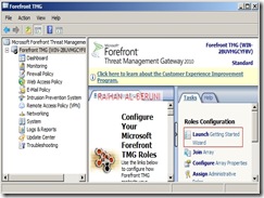
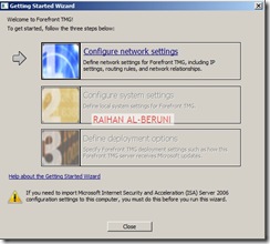
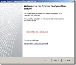
Install Forefront TMG using Step by Step Guide Lines. Open TMG Management console, Launch Getting started Wizard. Configure network Settings. Select back Firewall.

1 2 3 4 5 6 7

Click Configure Systems Settings.

8 9 10

Click Define Deployment Options.

11 12 13 14 15 16 17 18

Click Close. Apply Changes and Click Ok.

Create connectivity with AD and DNS.

24

Add and Verify IP addresses of internal (10.10.10.0/24) and perimeter network (192.168.100.0/24).

25

Add Network Rules:

Create Network Rule. To do that click on Networking>Network Rules>Create a New Network Rule Wizard.

1 2 3 4 5

Here, Rules 1 to 4 will created by default while initial configuration as shown below. You have to  create rule 5 and 6 by repeating above steps.

21

Configure Firewall Rules:

Actions Allow
Protocols DNS, Kerberos-Sec(TCP), Kerberos-Sec (UDP),Kerberos-Admin (UDP), LDAP, LDAP (UDP), LDAP (Global catalog), Microsoft CIFS (TCP) ,Microsoft CIFS (UDP), NTP (UDP), PING, RPC (All Interface)
Source DC, Front-End TMG
Destination DC, Front-End TMG
Conditions All Users

Now Publish DNS for perimeter network.  Right Click on Firewall Policy, Click New, Click Access Policy, Name new access policy. On the selected protocol add DNS, Kerberos-Sec(TCP), Kerberos-Sec (UDP),Kerberos-Admin (UDP), LDAP, LDAP (UDP), LDAP (Global catalog), Microsoft CIFS (TCP) ,Microsoft CIFS (UDP), NTP (UDP), PING, RPC (All Interface), Click next.

On the Access Rules Sources, Click Add, Select Computers, Click New, Type Netbios name of DC and Type IP, Click Ok. Select DC and Click Add. Repeat this process for Front-End TMG server i.e. add name and IP of front-end TMG server and Click Add.

On the Access Rule Destinations, Click Add, from the computers list add DC and front-End TMG servers. Click Next and Click Finish. Apply changes and click ok.

Create an Access Rule allowing all outbound traffic to go from internal to perimeter.

Actions Allow
Protocols All Outbound Traffic
Source Internal
Destination Perimeter
Conditions All Users

Create another access rule allowing HTTP and HTTPS to go from internal to perimeter and external.

Actions Allow
Protocols HTTP, HTTPS
Source Internal
Destination External
Conditions All Users

19

Configure Front-End Forefront TMG  Server:

Prepare another Windows Server 2008 x64 computer. Log on as an administrator. Define internal and external IP addresses as shown below.

Internal TCP/IP property:

3

External TCP/IP property

4

Open Command prompt>type following command to add persistent Routing:

c:>Route Add –P DestinationIP DestinationMask  SourceIP

1

c:>Route Print

2

Add Front-End TMG as domain member. Follow same installation and initial
configuration options shown in back-end TMG server.  There are only two differences while initial Network Settings configuration that are selecting internal (192.168.100.0/24) and external (203.17.x.x/24) network. Those are shown below.

16

17

Create Connectivity Verifier with AD, DNS and Web.

5

Networking>networks>internal>Add 10.10.10.0/24 and 192.168.100.0/24 as internal IP. Make sure internal IP and perimeter IP of back-end server are both internal IP of Front-end server. keep default routing rules in Front-End TMG. Configure property of internal network.

6

911

13

1012

Verify Network Rules:

7

Configure firewall to allow HTTP/HTTPS : Firewall Policy>New>Access policy>Allow HTTP and HTTPS for all users. Do not Allow all outbound traffic to go from internal to external in Front-End Server. Only specific ports and protocols should be allowed.

8

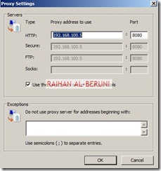
Test Firewall: Log on to a computer in internal network behind Back-End Firewall. Setup Proxy in IE as shown below and browse internet.

14 15

Placing Front-End Server(s) or a member server in DMZ:

One you have completed above steps, you are ready to place any Front-End server(s) such as Exchange CAS, OCS 2007 and SharePoint Servers  in DMZ/Perimeter. You need to import certificates from Enterprise Root CA placed in internal network (behind Back-End TMG) to Front-End TMG server to publish secure web sites such as OWA, Outlook Anywhere or OCS. All Publishing Rules Applied in Front-End TMG server. Here, I am not writing OWA or Anywhere because it would redundant for me to write again as I have shown all these in my previous posting. Visit the links mentioned below.

Prerequisite for placing a member server in DMZ: A member server must have following TCP/IP configuration to work in perimeter.

IP 192.168.100.0/24 (Perimeter IP Range)
DG 192.168.100.5 (Internal IP of Front-END TMG server)
DNS 10.10.10.5 (Internal DNS)
2nd DNS 203.17.x.x (Public DNS)
Routing As Mentioned in Persistent Routing Section of this Blog

Posted in TUTORIALS | Tagged: , , , , , , , , , , , , , , , , , , , , , , , , , , | Leave a Comment »

How to configure Windows Server Update Services (WSUS) to use BranchCache

Posted by Alin D on September 24, 2010

What is branchCache? BranchCache™ is a new feature in Windows® 7 and Windows Server® 2008 R2 that can reduce wide area network (WAN) or bandwidth utilization and enhance network application responsiveness when users access content in a central office from branch office locations. When you enable BranchCache, a copy of the content that is retrieved from the Web server or file server is cached within the branch office. If another client in the branch requests the same content, the client can download it directly from the local branch network without needing to retrieve the content by using the Wide Area Network (WAN).

How Branchcache works? When a Windows 7 Client from a branch office request data such as WSUS content to a head office Server then server check authentication and authorise data to pass on to the client. This is an ordinary communication happens without branchcache also.

But with branchcache, The client uses the hashes in the metadata to search for the file in the Hosted Cache server. Because this is the first time any client has retrieved the file, it is not already cached on the local network. Therefore, the client retrieves the file directly from the content server. The Hosted Cache server connects to the client and retrieves the set of blocks that it does not have cached.

When a second Windows 7 client from the same branch requests the same WSUS content from the content server or WSUS server. The content server authorizes the user/client and returns content identifiers. The second client uses these identifiers to request the data from the Hosted Cache server residing in branch. This time, it does not retrieve data from the DFS share residing in head office.

To configure a Web server or an application server that uses the Background Intelligent Transfer Service (BITS) protocol, you must install the BranchCache feature using server manager. To configure a file server to use BranchCache, you must install the BranchCache for Network Files feature and configure the server using Group Policy. This article discuss and show how to configure WSUS to use  branchcache. The followings are the steps involve in head office and Branch Offices.

Head Office:

  1. Install and configure back end SQL Server
  2. Create DFS share
  3. Install and configure front end WSUS Server
  4. Configure GPO for WSUS client

Branch Office:

  1. Install and configure Branchcache File Server
  2. Configure GPO for Branchcache
  3. Install and configure front end WSUS server
  4. Configure GPO for WSUS client

Installing BranchCache File Server

1. Click Start, point to Administrative Tools, and then click Server Manager.

2. Right-click Roles and then click Add Roles.

3. In the Add Features Wizard, select File Server and BranchCache for network files and then click Next.

4. In the Confirm Installation Selections dialog box, click Install.

5. In the Installation Results dialog box, confirm that BranchCache installed successfully, and then click Close.

Using Group Policy to configure BranchCache

1. Open the Group Policy Management Console. Click Start, point to Administrative Tools, and then click Group Policy Management Console.

2. Select the domain in which you will apply the Group Policy object, or select Local Computer Policy.

3. Select New from the Action menu to create a new Group Policy object (GPO).

4. Choose a name for the new GPO and click OK.

5. Right-click the GPO just created and choose Edit.

6. Click Computer Configuration, point to Policies, Administrative Templates, Network, and then click Lanman Server.

7. Double-click Hash Publication for BranchCache.

8. Click Enabled.

9. Under Options, choose one of the following Hash publication actions:

a. Allow hash publication for all file shares.

b. Allow hash publication for file shares tagged with “BranchCache support.”

c. Disallow hash publication on all file shares.

10. Click OK.

Using the Registry Editor to configure disk use for stored identifiers

1. Open an elevated command prompt (click Start, click All Programs, click Accessories, right-click Command Prompt, and then click Run as administrator).

2. At the command prompt, type Regedit.exe, and then press Enter.

3. Navigate to HKLMCurrentControlSetServiceLanmanServerParameters.

4. Right-click the HashStorageLimitPercent value, and then click Modify.

5. In the Value box, type the percentage of disk space that you would like BranchCache to use. Click OK.

6. Close the Registry Editor.

Setting the BranchCache support tag on a file share

1. Click Start, point to Administrative Tools, and then click Share and Storage Management.

2. Right-click a share and then click Properties.

3. Click Advanced.

4. On the Caching tab, select Only the files and programs that users specify are available offline.

5. Select Enable BranchCache, and then click OK.

6. Click OK, and then close the Share and Storage Management Console.

To replicate cryptographic data

1. Open an elevated command prompt (click Start, click All Programs, click Accessories, right-click Command Prompt, and then click Run as administrator).2. At the command prompt, type netsh branchcache set key passphrase=“MY_PASSPHRASE”, and then press Enter. Choose a phrase known only to you. Repeat this process using the same phrase on all computers that are participating in the cluster.

Client configuration using Group Policy

1. Click Start, point to Administrative Tools, and click Group Policy Management Console.

2. In the console tree, select the domain in which you will apply the GPO.

3. Create a new GPO by selecting New from the Action menu.

4. Choose a name for the new GPO, and then click OK.

5. Right click the GPO you created and choose Edit.

6. Click Computer Configuration, point to Policies, Administrative Templates: Policy definitions (ADMX files) retrieved from the local machine, Network, and then click BranchCache.

7. Double-click Turn on BranchCache.

8. Click Enabled, and then click OK.

9. To use Distributed Cache mode, double-click Turn on BranchCache – Distributed Caching mode, click Enabled, and then click OK.  or

To use Hosted Cache mode, double-click Turn on BranchCache – Hosted cache mode, click Enabled, and then click OK.

10. To enable BranchCache for SMB traffic, double-click BranchCache for network files, click Enabled, select a latency value under Options, and then click OK.

Configuring a Branch WSUS server to use BranchCache

In addition to enabling BranchCache in your environment, the WSUS server must be configured to store update files locally (both the update metadata and the update files are downloaded and stored locally on the WSUS server). This ensures that the clients get the update files from the WSUS server rather than directly from Microsoft Update.

Install SQL Server 2005/2008 with Management Studio Express on the back-end computer

  1. Click Start, point at All Programs, point at SQL Server 2005
    >, point at Configuration Tools, and select SQL Server Surface Area Configuration.
  2. Choose Surface Configuration for Services and Connections.
  3. In the left window, click the Remote Connections node.
  4. Select Local and remote connections and then select Using TCP/IP only.
  5. Click OK to save the settings.

To ensure administrative permissions on SQL Server

  1. Start SQL Server Management Studio (click Start, click Run, and then type sqlwb).
  2. Connect to the SQL Engine on the server where SQL Server 2005 was installed in Step 1.
  3. Select the Security node and then select Logins.
  4. The right pane will show a list of the accounts that have database access. Check that the person who is going to install WSUS 3.0 on the front-end computer has an account in this list.
  5. If the account does not exist, then right-click the Logins node, select New Login, and add the account.
  6. Set up this account for the roles needed to set up the WSUS 3.0 database. The roles are either dbcreator plus diskadmin, or sysadmin. Accounts belonging to the local Administrators group have the sysadmin role by default.

Install Branch WSUS Server

To install WSUS on the front-end computer At the command prompt, navigate to the folder containing the WSUS Setup program, and type:

WSUSSetup.exe /q FRONTEND_SETUP=1 SQLINSTANCE_NAME=serverinstance CREATE_DATABASE=0

Here, Serverinstance is the name of the remote SQL server that is holding the instance of WSUS database. If you do not want silent installation then don’t use /q switch and follow WSUS installation link

Important! Microsoft recommend 1GB free space for Systems Partition and 30GB for WSUS contents. But this minimum recommended space will create havoc when WSUS log, database log and content grow over the years. So, I used 50GB as systems partition and 100GB as WSUS contents in DFS share.

To configure the proxy server on WSUS front-end servers

  1. In the WSUS administration console, select Options, then Update Source and Proxy Server.
  2. Select the Proxy Server tab, then enter the proxy server name, port, user name, domain, and password, then click OK.
  3. Repeat this procedure on all the front-end WSUS servers.

To specify where updates are stored

  1. In the left pane of the WSUS Administration console, click Options.
  2. In Update Files and Languages, click the Update Files tab.
  3. If you want to store updates in WSUS, select the Store update files locally on this server check box.

To specify whether updates are downloaded during synchronization or when the update is approved

  1. In the left pane of the WSUS Administration console, click Options.
  2. In Update Files and Languages, click the Update Files tab.
  3. If you want to download only metadata about the updates during synchronization, select the Download updates to this server only when updates are approved check box.

To specify language options

  1. In the left pane of the WSUS Administration console, click Options.
  2. In Update Files and Languages, click the Update Languages tab.
  3. In the Advanced Synchronization Options dialog box, under Languages, select one of the following language options, and then click OK.
  4. Select Download updates only in these languages: This means that only updates targeted to the languages you select will be downloaded during synchronization.

How to configure automatic updates by using Group Policy

Log on to Domain Controller using Administrative Privilege. Open GPO management Console>Select Organisational unit>Right client>create and link a new GPO> Name it as WSUS policy>right click>Edit. Go to Computer ConfigurationAdministrative TemplatesWindows ComponentsWindows Updates

Now Specify Client target group, Intranet update server location i.e. http://servername:8530 , update schedule, installation schedule.

To set up a DFS share

Note:This DFS share will be used by all front end WSUS servers.

  1. Go to Start, point at All Programs, point at Administrative Tools, and click Distributed File System.
  2. You will see the Distributed File System management console. Right-click the Distributed File System node in the left pane and click New Root in the shortcut menu.
  3. You will see the New Root Wizard. Click Next.
  4. In the Root Type screen, select Stand-alone root as the type of root, and click Next.
  5. In the Host Server screen, type the name of the host server for the DFS root or search for it with Browse, and then click Next.
  6. In the Root Name screen, type the name of the DFS root, and then click Next.
  7. In the Root Share screen, select the folder that will serve as the share, or create a new one. Click Next.
  8. In the last screen of the wizard, review your selections before clicking Finish.
  9. You will see an error message if the Distributed File System service has not yet been started on the server. You can start it at this time.
  10. Make sure that the domain account of each of the front-end WSUS servers has change permissions on the root folder of this share.

Important! If you are using a DFS share, be careful when uninstalling WSUS from one but not all of the front-end servers. If you allow the WSUS content directory to be deleted, this will affect all the WSUS front-end servers.

To configure IIS for remote access on the front-end WSUS servers

  1. On each of the servers,
    go to Start, point at All Programs, point at Administrative Tools, and click Internet Information Services (IIS) Manager.
  2. You will see the Internet Information Services (IIS) Manager management console.
  3. Click the server node, then the Web Sites node, then the node for the WSUS Web site (either Default Web Site or WSUS Administration).
  4. Right-click the Content node and select Properties.
  5. In the Content Properties dialog box, click the Virtual Directory tab. In the top frame you will see The content for this resource should come from:
  6. Select A share located on another computer and fill in the UNC name of the share.
  7. Click Connect As, and enter the user name and password that can be used to access that share.
  8. Be sure to follow these steps for each of the front-end WSUS servers that are not on the same machine as the DFS share.

To move the content directories on the front-end WSUS servers

  1. Open a command window.
  2. Go to the WSUS tools directory on the WSUS server:cd Program FilesUpdate ServicesTools
  3. Type the following command:wsusutil movecontent DFSsharename logfilenamewhere DFSsharename is the name of the DFS share to which the content should be moved, and logfilename is the name of the log file.

To configure Network Load Balancing

1. Enable Network load balancing

  • a) Click Start, then Control Panel, Network Connections, Local Area Connection, and click Properties.
  • b) Under This connection uses the following items, you may see an entry for Network Load Balancing. If you do not, click Install, then (on the Select Network Component Type screen) select Service, then click Add, then (on the Select Network Service screen) select Network Load Balancing, then OK.
  • c) On the Local Area Connection Properties screen, select Network Load Balancing, and then click OK.

2. On the Local Area Connection Properties screen, select Network Load Balancing, and then click Properties.

3. On the Cluster Parameters tab, fill in the relevant information (the virtual IP address to be shared among the front end computers, and the subnet mask). Under Cluster operation mode, select Unicast.

4. On the Host Parameters tab, make sure that the unique host identifier is different for each member of the cluster.

5. On the Port Rules tab, make sure that there is a port rule specifying single affinity (the default). (Affinity is the term used to define how client requests are to be directed. Single affinity means that requests from the same client will always be directed to the same cluster host.)

6. Click OK, and return to the Local Area Connection Properties screen.

7. Select Internet Protocol (TCP/IP) and click Properties, and then click Advanced.

8. On the IP Settings tab, under IP addresses, add the virtual IP of the cluster (so that there will be two IP addresses). This should be done on each cluster member.

9. On the DNS tab, clear the Register this connection’s addresses in DNS checkbox. Make sure that there is no DNS entry for the IP address.

Posted in TUTORIALS | Tagged: , , , , , , , , , , , , , , , , , , , , , , , , , , , , , , , , , , , , , , , , | Leave a Comment »

How to setup a new Windows 2008 R2 Network Load Balancing

Posted by Alin D on September 10, 2010

How to setup a new Windows 2008 R2 Network Load Balancing.

1- Install and configure Network Load Balancing (NLB). To perform the following procedures you must use an account that belongs to the local Administrators security group on each host. Perform the following procedures in both hosts.

  • Click Start, click Administrative Tools, and then click Server Manager.
  • In the Features Summary area of the Server Manager main window, click Add Features.
  • In the Add Features Wizard, select the Network Load Balancing check box.
  • Click Install.
  • Alternatively, you can install NLB by typing the following command (You must run the cmd with elevated rights – Right click and choose the option run as Administrator): “servermanagercmd.exe -install nlb“.
  • After installing NLB, check the properties of your network adapter for the NLB option.
  • 2- Create the new NLB cluster (Perform the following steps in one of the nodes).

  • To open Network Load Balancing Manager, Right-click Network Load Balancing Clusters, and then click New Cluster.
  • To connect to the host that is to be a part of the new cluster, in the Host text box, type the name of the host, and then click Connect.
  • Select the interface that you want to use with the cluster, and then click Next. (The interface hosts the virtual IP address and receives the client traffic to load balance.)
  • In Host Parameters, select a value in Priority (Unique host identifier). This parameter specifies a unique ID for each host. The host with the lowest numerical priority among the current members of the cluster handles all of the cluster’s network traffic that is not covered by a port rule.
    You can override these priorities or provide load balancing for specific ranges of ports by specifying rules on the Port rules tab of the Network Load Balancing Properties dialog box.
    In Host Parameters, you can also add dedicated IP addresses, if necessary.
  • Click Next to continue.
  • In Cluster IP Addresses, click Add and type the cluster IP address that is shared by every host in the cluster. NLB adds this IP address to the TCP/IP stack on the selected interface of all hosts that are chosen to be part of the cluster. (NLB does not support Dynamic Host Configuration Protocol (DHCP). NLB disables DHCP on each interface that it configures, so the IP addresses must be static.)
  • Click Next to continue.
  • In Cluster Parameters, select values in IP Address and Subnet mask (for IPv6 addresses, a subnet mask value is not needed). Type the full Internet name that users will use to access this NLB cluster.
  • In Cluster operation mode, click Unicast to specify that a unicast media access control (MAC) address should be used for cluster operations. In unicast mode, the MAC address of the cluster is assigned to the network adapter of the computer, and the built-in MAC address of the network adapter is not used. We recommend that you accept the unicast default settings.
  • Click Next to continue.
  • In Port Rules, click Edit to modify the default port rules, if needed.
  • To add more hosts to the cluster, right-click the new cluster, and then click Add Host to Cluster. Configure the host parameters (including host priority, dedicated IP addresses, and load weight) for the additional hosts by following the same instructions that you used to configure the initial host. Because you are adding hosts to an already configured cluster, all the cluster-wide parameters remain the same.
  • DONE!!!

    Refrences:
    Technet Network Load Balancing

    Posted in TUTORIALS, Windows 2008 | Tagged: , , , , , , , , , , , | Leave a Comment »

    Configuring Virtual Networks With Hyper-V

    Posted by Alin D on September 8, 2010

    If you’ve ever worked with Microsoft’s Virtual PC or Virtual Server, then you know that those products work in the same way as any other Windows application. They sit on top of the host operating system, and all of the virtual machine’s hardware calls are passed through the host operating system, which manages the server’s hardware usage. Hyper-V takes a completely different approach to virtualization though, and this means that network communications are implemented in a much different way than they were in Microsoft’s other virtualization products. In this article, I will show you how networking works in Hyper-V.

    The Virtual Switch

    What really sets Hyper-V apart from Microsoft’s other virtualization products is that virtual machines perform much better because they can communicate with the server’s hardware directly rather than having to pass hardware requests through the host operating system (although there are some exceptions to this). Of course you can’t just bombard a network adapter with simultaneous traffic from multiple virtual machines. There has to be a way of managing the traffic. To get around this problem, Microsoft has introduced the concept of the virtual switch.

    To understand how this is possible, you have to realize that Hyper-V is not a Windows Server 2008 add-on, but rather is a part of the operating system. When you install the Hyper-V role, the hyper visor is placed “underneath” the Windows 2008 operating system. The existing operating system (known as the host operating system) is placed into something called the parent partition, and each guest operating system is placed into a separate child partition.

    To make this type of architecture possible, Microsoft had to unbind the host operating system’s TCP/IP stack from the server’s NIC. In doing so, they have created an additional layer of abstraction known as the virtual switch. The virtual switch is the only networking component that is bound to the physical network adapter. The parent partition and the child partitions use virtual network adapters (known as vNICs), which communicate with the virtual switch using Microsoft’s Virtual Network Switch Protocol.

    I realize that this description may be difficult to follow, so I have created the diagram shown in Figure A as a way of helping you to understand the architecture.

    Figure A This is what the virtual switch architecture looks like.

    Additional Virtual Switches

    Hyper-V allows you to create additional virtual switches beyond the one that I just talked about. To do so, open the Hyper-V Manager and then click on the Virtual Network Manager link. Upon doing so, Windows will display the Virtual Network Manager screen, shown in Figure B.

    Figure B The Virtual Network Manager allows you to create additional virtual switches.

    If you look at the figure above, you can see that the default virtual switch is bound to my physical network adapter. You also have the option of creating a new virtual network, which is the same as creating a new virtual switch. As you can see in the figure, there are three different types of virtual networks that you can create.

    Your first option is to create an external virtual network. Doing so creates a virtual switch through which virtual machines can access your entire network, and even the Internet assuming that you have the necessary infrastructure in place.

    One thing that you do need to know about external virtual networks is that they must be bound to a physical network adapter. Additionally, each physical network adapter can only be used for a single virtual network. Therefore, if you are creating a secondary external virtual network then you’re going to need a secondary NIC that you can bind the new external virtual network to.

    Your next option is to create an internal virtual switch. An internal virtual switch is not capable of accessing the yarn that, or even your private network as a whole. It serves primarily as a mechanism for allowing communications between the virtual machines that are hosted on the server. Additionally, an internal virtual network can facilitate communications between the host operating system and the guest operating systems that are running on it.

    Your third option is to create a private virtual network. A private virtual network can only be used to facilitate communications between the virtual machines that are hosted on the current server. Private virtual networks can not access the outside world, nor can they access the host operating system.

    Conclusion

    In this article, I have explained that under normal circumstances the virtual machines that require access your network typically share a single NIC. I then went on to show you how Windows manages the communications for all of your virtual machines, and how you can create an external virtual network that takes advantage of additional NICs installed in your server.

    Posted in TUTORIALS, Windows 2008 | Tagged: , , , , , , , , , , , , , , , , , , , , , , , , , , , , | Leave a Comment »

    Microsoft Refused to Patch Office XP

    Posted by Alin D on August 30, 2010

    Microsoft Refused to Patch Office XP


    Microsoft said it would not patch a vulnerability in Office XP because creating a fix was “infeasible.”

    The omission makes users running Office XP vulnerable to attack unless they take additional steps on their own.

    Office XP, which debuted in March 2001, remains on Microsoft’s list of supported suites — users will continue to receive security updates through mid-July 2011. But on Tuesday, Microsoft said a COM (component object model) validation vulnerability in the aged suite couldn’t be patched.

    The decision was explained in one of the 10 updates Microsoft issued yesterday that patched a record-tying 34 vulnerabilities.

    “The architecture to properly support the fixes to correct validation does not exist on Microsoft Office XP, making it infeasible to build the fixes for Microsoft Office XP products to eliminate the vulnerability,” said Microsoft in the MS10-036 security bulletin. “To do so would require rearchitecting a very significant amount of the Microsoft Office XP products, not just the affected components.”

    Even if it managed to rework Office XP, Microsoft said the effort would “sufficiently introduce an incompatibility with other applications that there would be no assurance that these Microsoft Office products would continue to operate as designed.”

    “This is another example of old software showing its age,” said Amol Sarwate, the manager of Qualys’ vulnerabilities research lab. “The interdependencies of those [.dll files] is almost impossible to patch without upgrading the whole platform.”

    Instead of an actual patch, Microsoft urged Office XP users to download and run an automated tool from its “Fit it” Library. The tool, said Microsoft, “provides similar protections against the vulnerability” as the patch offered to people running Office 2003 and Office 2007.

    “Microsoft built a shim to protect Office XP,” said Richie Lai, Qualys’ director of vulnerability research. “It’s a workaround, but Microsoft’s not fixing the vulnerable code.

    The Fix it shim can be downloaded from Microsoft’s support site.

    This was the second time since September 2009 that Microsoft has passed on providing a patch. Then, Microsoft declined to patch two bugs in the implementation of TCP/IP in Windows 2000 and Windows XP. TCP/IP is the Web’s default suite of connection protocols. Microsoft used the same rationale last September as it did Tuesday to explain why it isn’t patching.

    “No, I wouldn’t call this a trend,” said Sarwate when asked whether the two incidents indicate a decision by Microsoft to refuse to patch older products.

    Additionally, users running Office 2003 or Office 2007 must upgrade those suites before applying Tuesday’s patch, Microsoft added. Office 2003 must be at Service Pack 3 (SP3), the latest major update from Microsoft, while Office 2007 must be at SP1 or SP2.

    Microsoft also said that it piggybacked other changes onto the MS10-036 updates for Office 2003 and Office 2007 that address problems that resulted when a Microsoft engineer added a single extraneous “&” character to a critical code development library.

    The company patched Active Template Library (ATL), a code library used by both Microsoft and third-party developers to build software, in an emergency July 2009 update.

    “This update includes a defense-in-depth change … that helps prevent components and controls built using vulnerable versions of ATL from being exploited in the Microsoft Office products,” said Microsoft.

    Although Microsoft didn’t tell Office XP users to upgrade, Qualys’ researchers did.

    “Older software has the highest number of vulnerabilities,” noted Lai. “Of the 14 vulnerabilities in Excel patched [Tuesday in MS10-038] 11 of them applied just to Office XP, but only three to the newer versions.”

    Want to share Windows 7 information with every reader, welcome to http://www.newton360.com to get more information, including Windows 7 news, tips, wallpapers and softwares…

    Posted in Security | Tagged: , , , , , , , , , , , , , , | Leave a Comment »