Windows Management and Scripting

A wealth of tutorials Windows Operating Systems SQL Server and Azure

Posts Tagged ‘corporate network’

Step by step guide to Configure Back-to-Back Firewall with Perimeter (DMZ) Topology

Posted by Alin D on September 25, 2010

Placing a firewall in a corporate network puts you in commanding position to protect your organisation’s interest from intruder. Firewall also helps you to publish contents or share infrastructure or share data securely with eternal entity such as roaming client, business partners and suppliers. Simply, you can share internal contents without compromise security. For example, publishing Exchange Client Access Server, OCS 2007 and SharePoint front-end server in the perimeter.

More elaborately, the front-end and the back-end topology is commonly seen in multi-tier applications where the user interacts with a front-end server (Example: CAS server) and that server interacts with a back-end Server (Example: HT server). In this exchange deployment scenario, users interact with a front-end CAS Web server placed in DMZ or perimeter to get Outlook Web Access for reading and sending email. That Web server must interact with the back-end mail server or HT server, but Internet users do not need to interact directly with the back-End HT server. The front-end and back-end server(s) does all these for you providing maximum security. visit Exchange 2010 deployment in different firewall scenario

In this article, I am going to illustrate Back-to-Back Firewall with DMZ. This topology adds content publishing to the back-to-back perimeter topology. By adding content publishing, sites and content that are developed inside the corporate network can be published to the server farm that is located in the perimeter network.The following illustration shows the back-to-back perimeter topology with content publishing.

image

Advantages
  1. Isolates customer-facing and partner-facing content to a separate perimeter network.
  2. Content publishing can be automated.
  3. If content in the perimeter network is compromised or corrupted as a result of Internet access, the integrity of the content in the corporate network is retained.
Disadvantages
  1. Requires more hardware to maintain two separate farms.
  2. Data overhead is greater. Content is maintained and coordinated in two different farms and networks.
  3. Changes to content in the perimeter network are not reflected in the corporate network. Consequently, content publishing to the perimeter domain is not a workable choice for extranet sites that are collaborative.

Assumptions:

  1. Internal IP range: 10.10.10.0/24
  2. Perimeter IP Range: 192.168.100.0/24
  3. Public IP:203.17.x.x/24

Note: In the production environment, perimeter IP must be public IP accessible from internet.

Computer Internal NIC Configuration External NIC Configuration
Back-End
TMG 2010
(two NICs)
IP: 10.10.10.2
Mask:255.255.255.0
DG:Null
DNS:10.10.10.5
IP:192.168.100.4
Mask:255.255.255.0
DG:192.168.100.5
DNS:Null
Front-End
TMG 2010
(Two NICs)
IP:192.168.100.5
Mask:255.255.255.0
DG:null
DNS:10.10.10.5
2nd DNS:203.17.x.x (public IP)
IP:203.17.x.x (public IP)
Mask:255.255.255.0
DG:203.17.x.1 (public DG)
DNS:203.17.x.x (public DNS)
DC IP:10.10.10.5
Mask:255.255.255.0
DG:10.10.10.2
DNS:10.10.10.5
Not Applicable

Routing Relation:

Back-end TMG Internal to Perimeter Perimeter to External

Perimeter to Internal

Route NAT (Default)

Route

Front-End TMG Internal to External
(All TMG Default)
NAT (Default)

Persistent Routing in Front-End TMG and all servers placed in perimeter/DMZ: You must add following routing table in front-end TMG server and all other servers placed in perimeter in elevated command prompt. To do that, just log on as administrator, open command prompt and type following and hit enter.

Route ADD –P 10.10.10.0 MASK 255.255.255.0 192.168.100.4

Configure Back-End TMG Server:

Log on to TMG Server using Administrative credentials and define internal IP as shown on TCP/IP property.

22

Define Perimeter IP As shown on TCP/IP property

23

Now add TMG serve
r as a domain member.
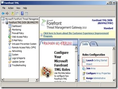
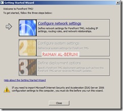
Install Forefront TMG using Step by Step Guide Lines. Open TMG Management console, Launch Getting started Wizard. Configure network Settings. Select back Firewall.

1 2 3 4 5 6 7

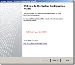
Click Configure Systems Settings.

8 9 10

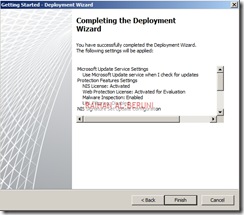
Click Define Deployment Options.

11 12 13 14 15 16 17 18

Click Close. Apply Changes and Click Ok.

Create connectivity with AD and DNS.

24

Add and Verify IP addresses of internal (10.10.10.0/24) and perimeter network (192.168.100.0/24).

25

Add Network Rules:

Create Network Rule. To do that click on Networking>Network Rules>Create a New Network Rule Wizard.

1 2 3 4 5

Here, Rules 1 to 4 will created by default while initial configuration as shown below. You have to  create rule 5 and 6 by repeating above steps.

21

Configure Firewall Rules:

Actions Allow
Protocols DNS, Kerberos-Sec(TCP), Kerberos-Sec (UDP),Kerberos-Admin (UDP), LDAP, LDAP (UDP), LDAP (Global catalog), Microsoft CIFS (TCP) ,Microsoft CIFS (UDP), NTP (UDP), PING, RPC (All Interface)
Source DC, Front-End TMG
Destination DC, Front-End TMG
Conditions All Users

Now Publish DNS for perimeter network.  Right Click on Firewall Policy, Click New, Click Access Policy, Name new access policy. On the selected protocol add DNS, Kerberos-Sec(TCP), Kerberos-Sec (UDP),Kerberos-Admin (UDP), LDAP, LDAP (UDP), LDAP (Global catalog), Microsoft CIFS (TCP) ,Microsoft CIFS (UDP), NTP (UDP), PING, RPC (All Interface), Click next.

On the Access Rules Sources, Click Add, Select Computers, Click New, Type Netbios name of DC and Type IP, Click Ok. Select DC and Click Add. Repeat this process for Front-End TMG server i.e. add name and IP of front-end TMG server and Click Add.

On the Access Rule Destinations, Click Add, from the computers list add DC and front-End TMG servers. Click Next and Click Finish. Apply changes and click ok.

Create an Access Rule allowing all outbound traffic to go from internal to perimeter.

Actions Allow
Protocols All Outbound Traffic
Source Internal
Destination Perimeter
Conditions All Users

Create another access rule allowing HTTP and HTTPS to go from internal to perimeter and external.

Actions Allow
Protocols HTTP, HTTPS
Source Internal
Destination External
Conditions All Users

19

Configure Front-End Forefront TMG  Server:

Prepare another Windows Server 2008 x64 computer. Log on as an administrator. Define internal and external IP addresses as shown below.

Internal TCP/IP property:

3

External TCP/IP property

4

Open Command prompt>type following command to add persistent Routing:

c:>Route Add –P DestinationIP DestinationMask  SourceIP

1

c:>Route Print

2

Add Front-End TMG as domain member. Follow same installation and initial
configuration options shown in back-end TMG server.  There are only two differences while initial Network Settings configuration that are selecting internal (192.168.100.0/24) and external (203.17.x.x/24) network. Those are shown below.

16

17

Create Connectivity Verifier with AD, DNS and Web.

5

Networking>networks>internal>Add 10.10.10.0/24 and 192.168.100.0/24 as internal IP. Make sure internal IP and perimeter IP of back-end server are both internal IP of Front-end server. keep default routing rules in Front-End TMG. Configure property of internal network.

6

911

13

1012

Verify Network Rules:

7

Configure firewall to allow HTTP/HTTPS : Firewall Policy>New>Access policy>Allow HTTP and HTTPS for all users. Do not Allow all outbound traffic to go from internal to external in Front-End Server. Only specific ports and protocols should be allowed.

8

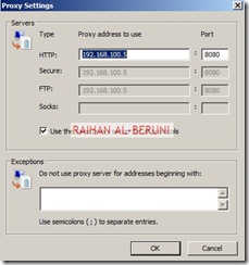
Test Firewall: Log on to a computer in internal network behind Back-End Firewall. Setup Proxy in IE as shown below and browse internet.

14 15

Placing Front-End Server(s) or a member server in DMZ:

One you have completed above steps, you are ready to place any Front-End server(s) such as Exchange CAS, OCS 2007 and SharePoint Servers  in DMZ/Perimeter. You need to import certificates from Enterprise Root CA placed in internal network (behind Back-End TMG) to Front-End TMG server to publish secure web sites such as OWA, Outlook Anywhere or OCS. All Publishing Rules Applied in Front-End TMG server. Here, I am not writing OWA or Anywhere because it would redundant for me to write again as I have shown all these in my previous posting. Visit the links mentioned below.

Prerequisite for placing a member server in DMZ: A member server must have following TCP/IP configuration to work in perimeter.

IP 192.168.100.0/24 (Perimeter IP Range)
DG 192.168.100.5 (Internal IP of Front-END TMG server)
DNS 10.10.10.5 (Internal DNS)
2nd DNS 203.17.x.x (Public DNS)
Routing As Mentioned in Persistent Routing Section of this Blog

Posted in TUTORIALS | Tagged: , , , , , , , , , , , , , , , , , , , , , , , , , , | Leave a Comment »

Windows User State Virtualization – Virtualizing Application State

Posted by Alin D on September 13, 2010

When a user roams from one computer to another on a corporate network, their basic need remains the same: to be able to perform their job. Redirecting folders like My Documents (where users should and usually do store work-related files) and Desktop (where users sometimes save important files so they can access them quickly) meets some of this need since it allows users to easily access work-related files from any computer on the network. But users sometimes want more than just access to their data—they also want the applications they use to work with such data to look, feel and behave exactly the same regardless of which computer they log on to.

For example, if a user customizes Microsoft Word on one machine then she may want the same customization to be visible when she logs on to a different machine and opens Word on it. Common customizations might include showing the Ribbon minimized, showing formatting marks, ignoring uppercase words during spell checks, and so on. Users who roam between machines are often annoyed if the applications they use aren’t set up exactly the same on each computer.

Per-user application customizations like these together comprise the state of the application. An application’s state can include both settings and data. Per-user application settings are stored in registry, generally within the user’s HKEY_CURRENT_USERS (HKCU) registry hive. Per-user application data consists of files stored on the user’s hard drive, and on Windows Vista and later such data is usually stored within the user’s profile in AppData, a hidden folder found under each user’s root profile folder. Let’s look at roaming per-user application data first.

Roaming Per-User Application Data

Per-user application data is stored in the AppData folder. Beneath the AppData folder are three subfolders described in Table 1 below.

Subfolder Purpose
Local Windows and application settings that either (a) are per-user settings but should not be roamed or (b) are per-machine settings and therefore cannot be roamed.
LocalLow Settings used by certain low-integrity processes such as Internet Explorer Protected Mode. These settings cannot be roamed.
Roaming Windows and application per-user settings that are capable of being roamed.

Table 1: Subfolders of USERPROFILEAppData

As Table 2 shows, the Local and Roaming subfolders in Windows Vista and later had their counterparts in Windows XP.

Windows Vista and later Windows XP
%USERPROFILE%AppDataLocal %USERPROFILE%Local SettingsApplication Data
%USERPROFILE%AppDataLocalLow (no counterpart in XP)
%USERPROFILE%AppDataRoaming %USERPROFILE%Application Data

Table 2: Application state folders in Windows Vista and later compared with Windows XP

What kind of Windows and application data is actually stored in the AppDataRoaming folder? Lots of stuff including network shortcuts, printer shortcuts, Send To shortcut menu items, Start menu recent items, Microsoft Office application templates and custom dictionaries, and so on. Figure 1 shows the AppDataRoaming folder and its subfolders on a Windows 7 machine with Office 2010 installed.


Figure 1: The AppDataRoaming folder and its subfolders on a Windows 7 machine with Office 2010 installed

The contents of this AppDataRoaming folder can be roamed in two ways:

  • It can redirected out of the user’s profile to a network share by using Folder Redirection (FR) (see Figure 2 below).
  • It can be roamed along with the rest of the user’s profile by using Roaming User Profiles (RUP).


Figure 2: The AppDataRoaming folder can be redirected using Folder Redirection

Roaming Per-User Application Settings

There are many, many more per-user settings stored in the registry however than there are per-user data files stored in the AppDataRoaming folder. These per-user are stored within the user’s HKCU registry hive, which is stored as a file named NTUSER.DAT in the root of each user’s profile, which means these settings can be roamed by using RUP. Examples of per-user Windows settings include such things as the user’s current theme, sound scheme, desktop background, screen saver, display settings, accessibility settings, regional and keyboard settings, problem reporting settings, Windows Explorer customization settings, Internet Explorer options, Windows Media Player settings, and so on.

Examples of per-user application settings for Office 2010 include security settings, Ribbon customizations, most recently used (MRU) entries, user name and initials for reviewing, and more. These application settings are found under HKCUSoftwareMicrosoftOffice and Figure 3 below shows some of the per-user application settings for Word 2010.


Figure 3: Per-user application settings for Word 2010

How to Roam Application State

Because application state (per-user application data and settings) are stored in two locations (data files in the AppDataRoaming folder and settings in the user’s HKCU registry hive) you have some choices on how to roam application state for your organization if this is needed. Specifically, you can:

  • Approach #1: Use RUP to roam both the user’s HKCU registry hive together with the AppDataRoaming folder within the user’s profile.
  • Approach #2: Use RUP to roam the user’s HKCU registry hive while using FR to redirect the AppDataRoaming folder out of the user’s profile to a network share.
  • Approach #3: Don’t use RUP, just use FR to redirect the AppDataRoaming folder out of the user’s profile to a network share.

Let’s look at the pros and cons of each of the above approaches.

Approach #1: Use RUP alone

The main advantage of this approach is that it keeps application data and application settings in sync with each other. This is because both the user’s HKCU registry hive and the contents of the AppDataRoaming folder are normally synced only at user logon and logoff. This can be important because some applications may not work properly and can even crash if the application’s settings stored in HKCU become out of sync with the application’s data stored in AppDataRoaming.

Another advantage of this approach has to do with poorly behaved applications that just don’t work right when certain subfolders of AppDataRoaming are roamed. In such cases you can use the “Exclude directories in roaming profile” policy setting to exclude these subfolders from being roamed with RUP (see Figure 4) which is found under Computer ConfigurationPoliciesAdministrative TemplatesSystemUser Profiles.


Figure 4: Policy setting for excluding user profile subfolders from being roamed with RUP

The main downside of this approach however is that it can increase logon/logoff times for users. This is because the contents of the AppDataRoaming folder can frequently change and can often grow quite large over time. The resulting increase in the size of user profiles means that when RUP is used the logon/logoff experience for users can become poor. Note that beginning with Windows 7 there is a new policy setting called “Background upload of roaming user profile’s registry file while user is logged on” found under User ConfigurationPoliciesAdministrative TemplatesSystemUser Profiles. By enabling and configuring this policy setting you can upload changes to roaming profiles in the background while users are logged on, and this can help reduce logon/logoff times for users (see Figure 5). But while frequently uploading roaming profiles in the background might lessen the chance of application data and settings getting out of sync, it doesn’t solve the problem completely and can also add a lot of additional traffic to your network.


Figure 5: Policy setting for enabling background upload of roaming profiles

Approach #2: Use RUP but use FR to redirect AppDataRoaming

The advantage of this approach is that redirecting the contents of the AppDataRoaming folder out of the user profile reduces the size of user profiles and thus can provide a much better logon/logoff experience for users than the previous approach above. In this scenario, RUP syncs the HKCU registry hive to a network share while Offline Files syncs the contents of the redirected AppDataRoaming folder to a different network share. Once again however, the problem becomes keeping application settings and data in sync with each other for applications that behave poorly when these become out of sync. In this case, another policy setting can come to the rescue, namely “Network directories to sync at logon/logoff time only” which is found under User ConfigurationPoliciesAdministrative TemplatesSystemUser Profiles. By enabling and configuring this policy setting, you can specify certain subfolders under AppDataRoaming as needed so that they sync using Offline Files only at logon/logoff (see Figure 6). Doing this for certain subfolders can help ensure that the data and settings for certain applications are always in sync with one another.


Figure 6: Policy setting for syncing specified redirected folders only at logon/logoff using Offline Files.

Approach #3: Use FR to redirect AppDataRoaming but don’t use RUP

Finally, what if users only need access to Word custom dictionaries and templates when they roam between computers, and not to other customization settings for Word? Since Word custom dictionaries and templates are stored in AppDataRoaming, could you simply use FR to redirect this folder to the network and not use RUP?

Nope. Don’t redirect AppDataRoaming using FR unless you are also using RUP. Otherwise you’re going to end up at the least with applications behaving strangely and possibly even crashing, and at worst lost data and lost productivity.

Conclusion: The Importance of Testing

The bottom line about virtualizing application state is that you must test your solution before deploying it in your production environment. In addition to the reasons mentioned above, this is also important for two additional reasons. First, most vendors who develop applications probably never bother to test their applications in different roaming environments to see if they actually roam properly. Even Microsoft has fallen down in this area at times. For example, when Office 2007 was released it was soon discovered that the configuration of the Quick Access Toolbar didn’t roam. Microsoft soon issued a hotfix for this issue, but this illustrates how easy it is for application vendors (even Microsoft) to fail to verify that all of an application’s per-user data and settings can roam properly.

And second, vendors may decide for reasons unknown to deliberately store certain user-configurable application settings outside of HKCU or to store certain user-configurable application files outside of the AppDataRoaming folder. For example, they might decide to store all application settings in HKLM instead of storing the user-configurable ones in HKCU. As a result, such applications may not behave properly in roaming user environments.

So test, test, test before you try and implement a USV solution that includes roaming application state!

Posted in TUTORIALS, Windows 2008 | Tagged: , , , , , , , , , , , , | Leave a Comment »

Implementing VDI using Windows Server 2008 R2 Remote Desktop Services and Hyper-V

Posted by Alin D on September 10, 2010

RDS VDI Functionality

An RDS-based VDI provides an environment that enables central storage, execution, and management of Windows desktops in a datacenter. An RDS VDI solution supports the creation and management of virtual desktop pools, and personal virtual desktops.

A virtual desktop pool is a collection of identical virtual desktops that are available for connection by multiple users. This type of virtual desktop does not maintain user state; instead it reverts back to its original state when a user logs off. A virtual desktop pool is applicable to users with the following characteristics:

  • Do not need a personalized desktop
  • Do not need offline access to virtual desktop
  • Do not need to save state between sessions
  • Need access to the virtual desktop from a collection of client devices

Examples of users that may require access to a virtual desktop pool are call-center workers, POS workers, and administrative office workers.

In contrast, a personal virtual desktop is configured for connection by a single user and maintains user state information when the user logs off. A personal virtual desktop pool is applicable to users with the following characteristics:

  • Need a personalized desktop
  • Need to save desktop state between sessions
  • Need administrative access to virtual desktop

Examples of users that may require access to a personal virtual desktop are offshore software developers and testers.

Core RDS VDI Components

Whether deploying a virtual desktop pool or personal virtual desktops using RDS-based VDI, specific core components are needed and additional components may be necessary depending on the complexity of the solution requirements. The core components required for any RDS-based VDI solution include the following:

  • RD Connection Broker
  • RD Session Host
  • RD Virtualization Host
  • RD Licensing Server

The RD Connection Broker builds on the functionality of the Windows Server 2008 TS Session Broker to manage not only session-based remote desktops, but also virtual desktops. The RD Virtualization Host (RDVH) is a new role added in Windows Server 2008 R2. The RD Virtualization Host role runs on Hyper-V hosts and serves to manage the state of virtual machines and connect users to virtual machines.

RD Connection Broker

The RD Connection Broker manages user requests for connection to session-based and virtual machine-based desktops. It tracks the user name for each connection as well as the connection identifier, connection state, and connection host for each connection to an RD Session Host or RD Virtualization Host server. The RD Connection Broker also provides the ability to load balance connections within RD Session Host and RD Virtualization Host server farms, by evenly distributing connections between RD Session Host and RD Virtualization Host servers using a relative server weight value. In addition, the RD Connection Broker enables disconnected users to reconnect to an existing session-based or virtual machine-based desktop.

RD Session Host

In a VDI environment, RD Session Host servers are configured to run in redirection mode, which disallows interactive user sessions. Instead, when a client requests a connection to a virtual desktop, the RD Session Host server role contacts the RD Connection Broker for the IP address of the virtual machine to which the user should connect and returns it to the client. The client then initiates an RDP connection to the virtual machine.

RD Virtualization Host

The RD Virtualization Host is installed on Hyper-V hosts to manage virtual machines in preparation for an RDP connection based on a request from the RD Connection Broker. In addition, the RD Virtualization Host monitors and reports on virtual machine guest sessions to the RD Connection Broker.

RD Licensing Server

If you have worked in a Microsoft Terminal Services environment, you are already familiar with Client Access Licenses (CALs). In Windows Server 2008 R2, an RDS CAL is required for each device or user that connects to RD Session Host or RD Virtualization Host servers. When a user or device attempts a connection through an RD Session Host server, it requires an RDS CAL. The RD Session Host server makes a request to an RD Licensing Server on behalf of the client. If an RDS CAL is available, it is issued to the client, which is then able to connect to the RD Session Host or RD Virtualization Host server.

Microsoft provides a grace period that begins when an RD Session Host server accepts the first client connection. However, after the grace period, each user or device must be issued an RDS CAL before it can connect to an RD Session Host or RD Virtualization Host server. In Windows Server 2008 R2, the grace period lasts 120 days.

If you already have Windows Server 2008 deployed and have Windows Server 2008 TS CALs, you do not need to purchase new CALs as both Windows Server 2008 TS CALs and Windows Server 2008 R2 RDS CALs allow a user or device the right to connect to Windows Server 2008 R2.

Other RDS VDI Components

There are several additional RDS components that may be needed to provide a complete VDI solution. These additional components include the following:

  • RD Web Access
  • RD Gateway
  • RemoteApp

RD Web Access

RD Web Access provides a web portal from which users can access session-based remote desktops, session-based remote applications, or virtual machine-based desktops. User requests for connection to session-based and virtual machine-based desktops made through RD Web Access are managed through the RD Connection Broker.

In Windows Server 2008 R2, RD Web Access allows the view of available remote desktops, remote applications, and virtual desktops to be customized based on user access. This means that a user will only be able to view and access those elements to which an administrator has specifically provided rights and permissions.

The RD Web Access portal also supports both private and public computer modes to control storage of sensitive information. For example, in private mode, RD Web Access cookies storing a user name expire in 4 hours. In public mode, they expire in 20 minutes.

RD Gateway

The RD Gateway is deployed at the edge of a corporate network and allows remote users to connect to resources deployed within a corporate intranet through a secure, encrypted connection. RD Gateway uses RDP over HTTPS to establish the secure connection between the remote user device and internal corporate resources.

RemoteApp

RemoteApp enables applications hosted on an RD Session Host server and virtual desktops hosted on an RD Virtualization Host server to be remotely accessed and integrated with a client desktop. For examples, using RemoteApp, it is possible to launch a remotely hosted application from an icon on the client desktop. When the application launches, an RDP session initiates to the application host and the application is presented on the local desktop in its own resizable window. If a user runs multiple RemoteApp applications, the applications can also share a single RDP session.

Remote Client Connection Sequence in Windows Server 2008 R2 RDS VDI

So how do RDS components work together to provide a remote client access to a virtual desktop within an Active Directory domain? Here is a brief explanation of the process assuming that RD Gateway and RD Web Access are deployed behind an external firewall and used to connect to a virtual desktop:

  1. A remote user opens a web browser and connects to the RD Web Access portal.
  2. RD Web Access requests the list of virtual desktop information to display from the RD Connection Broker.
  3. The RD Connection Broker checks virtual desktop permissions in Active Directory, and then provides the information back to the RD Web Access site.
  4. The users’ browser displays the virtual desktop information from the RD Web Access site.
  5. After the user selects a virtual desktop, the Remote Desktop Client (RDC) opens a connection to the RD Gateway.
  6. The RD Gateway forwards the connection to the RD Session Host server running in redirection mode.
  7. The RD Session Host server requests that the RD Connection Broker prepare the virtual desktop and return its IP address.
  8. The RD Connection Broker queries AD to verify user credentials and personal virtual desktop information associated with the user, if necessary.
  9. The RD Connection Broker requests that the RD Virtualization Host server start the virtual desktop if it is not running, and then returns the virtual desktop IP address to the RD Session Host server.
  10. The RD Session Host server returns the virtual desktop IP address to the Remote Desktop Client running on the users’ computer.
  11. The Remote Desktop Client connects to the virtual desktop through the RD Gateway.

Since there are many different network configurations in which the RD Gateway and other RDS VDI components can be deployed, the connection sequence may slightly vary. For additional information on RD Gateway deployment configurations, you can check out the Microsoft RDS Team blog entry here.

Conclusion

In Windows Server 2008 R2, the RD Connection Broker has been extended to manage not only session-based remote desktops, but also virtual machine-based desktops running on Hyper-V. With this new feature and the addition of the RD Virtualization Host component, it is now possible to build a VDI for small or medium environments using only Windows Server 2008 R2 RDS components. For large deployments, a Microsoft RDS-based VDI solution can still be integrated with Citrix XenDesktop to provide an enterprise scale infrastructure.

Posted in Windows 2008 | Tagged: , , , , , , , , , , , , , , , , , , , , , , , , , , , | Leave a Comment »

Using the Microsoft Offline Virtual Machine Servicing Tool Version 2.1 with WSUS (Part 1)

Posted by Alin D on September 10, 2010

Introduction

In Part 1 of this article, you will learn how the Microsoft Offline Virtual Machine Servicing Tool 2.1 (OVMST 2.1) integrates with System Center Virtual Machine Manager 2008 R2 and Windows Software Update Services in order to update offline virtual machines. In Part 2 of the article, you will learn how to configure WSUS 3.0 SP2, VMM 2008 R2, OVMST 2.1, and virtual machine clients to perform offline virtual machine updates.

What is an Offline Virtual Machine?

One of the key components in an enterprise virtualization infrastructure is a repository of components that are used to efficiently and rapidly provision virtual machines. In Microsoft System Center Virtual Machine Manager 2008 R2 (VMM 2008 R2), the repository is called a VMM library. A VMM library stores components such as:

  • Hardware profiles
  • Guest operating system profiles
  • Virtual machine templates
  • Virtual hard disks
  • Virtual floppy disks
  • PowerShell scripts
  • Sysprep files
  • Offline virtual machines

An offline virtual machine is a Windows virtual machine that is stored in a VMM library in an exported state. An exported virtual machine consists of one or more virtual hard disks (VHDs) and a configuration file (.EXP file extension). The configuration file contains virtual machine settings in a format that Hyper-V can use to re-create the virtual machine through the import function. It is important to note that the virtual machine VHDs are not altered during the export process. Once exported, the offline virtual machine configuration file is stored in the VMM library database along with a link to the VHD files. The virtual machine VHDs are stored in a VMM library share.

The Problem with Offline Virtual Machines

The assumption that goes along with creating and storing an offline virtual machine in the VMM library is that it will be redeployed to a Hyper-V host (or Virtual Server 2005 R2 SP1) at some later point in time. Of course, if several weeks or months elapse before the offline virtual machine is redeployed; it will likely require several operating system and application patches to restore it to an updated state. In most enterprises today, only updated systems are allowed to be connected to the corporate network. Therefore, before deploying the virtual machine back into the production network, it would have to be deployed to a quarantined network to perform the updates. Although this is a feasible approach, it would be more desirable to periodically update offline virtual machines, so that when it is time to redeploy into production only a minimal number of updates are required (if any) to bring it up-to-date. Microsoft addressed this issue with the development of the Offline Virtual Machine Servicing Tool (OVMST) which provides automation of the offline virtual machine update process.

OVMST 2.1 Overview

OVMST 2.1 is a Microsoft Solution Accelerator product released in December 2009. It is available as a free download from the Microsoft website. OVMST 2.1 provides the ability to orchestrate the automated update of offline virtual machines stored in a VMM library when configured and integrated with System Center Virtual Machine Manager 2008 (or R2), System Center Configuration Manager 2007 (SP1, R2, or SP2), and/or Windows Software Update Server (WSUS) 3.0 SP1 or later version. Perhaps obvious, but still worth mentioning, this infrastructure requires Active Directory Domain Services (ADDS), and that servers and virtual machines are members of the AD domain.

OVMST 2.1 supports Hyper-V running on Windows Server 2008 SP2, Hyper-V R2 running on Windows Server 2008 R2, and Virtual Server 2005 R2 SP1. However, Virtual Server 2005 R2 SP1 cannot serve as a host for virtual machines exported from Hyper-V or Hyper-V R2 since the export format is incompatible.

In addition, OVMST 2.1 can orchestrate offline virtual machine updates for the following Windows guest operating systems:

  • Windows XP Professional SP2 (64-bit)
  • Windows XP Professional SP3 (32-bit)
  • Windows Server 2003 SP2 (32 and 64-bit)
  • Windows Server 2003 R2 SP2 (32 and 64-bit)
  • Windows Vista SP1 and SP2 (32 and 64-bit)
  • Windows Server 2008 SP2 (32 and 64-bit)
  • Windows Server 2008 R2 (64-bit)
  • Windows 7 (32 and 64-bit)

If Windows 7 or Windows Server 2008 R2 offline virtual machines need to be updated using OVMST 2.1 and WSUS, or in conjunction with System Center Config Mgr 2007 SP2, then WSUS 3.0 SP2 is a requirement. WSUS 3.0 SP2 is also available as a free download from the Microsoft website.

OVMST 2.1 Components

OVMST 2.1 is composed of a management console, a workflow engine, and a collection of scripts used by the workflow engine to perform the various tasks that are required during an update cycle. In order to execute processes on remote client virtual machines (offline virtual machines temporarily deployed on a Hyper-V host to perform updates), OVMST 2.1 relies on the use of the PsExec utility developed by Mark Russinovich, formerly from Winternals, and currently a Technical Fellow in the Platform and Services Division at Microsoft. The PsExec utility must be downloaded separately and installed on the same machine as the OVMST 2.1 application.

The OVMST 2.1 management console seen in Figure 1 is an MMC-based application that allows configuration of the tool, creation of virtual machine groups, assignment of virtual machines to virtual machine groups, as well as creation and scheduling of update servicing jobs.


Figure 1: OVMST 2.1 Management Console

OVMST 2.1 uses servicing jobs to manage the update operations. A servicing job combines configuration settings with Windows batch files, VB scripts, and Windows PowerShell cmdlets that make up a task managed by the Windows Task Scheduler. Specifically, a servicing job defines the following configuration settings:

  • Software update management system (System Center Config Mgr or WSUS)
  • Target offline virtual machines
  • Virtual network to connect virtual machines for updates
  • Hyper-V maintenance hosts to deploy the virtual machines
  • Account credentials with administrative permissions on the virtual machines
  • Execution schedule

A servicing job can target one or more offline virtual machines organized in virtual machine groups created within OVMST 2.1. A virtual machine group allows you to assign specific virtual machines to a collection that is then easily selected as the target of a specific servicing job.

Offline Virtual Machine Update Workflow

The main tasks that are performed during an OVMST 2.1 servicing job include the following steps:

  • Deploying a virtual machine from a VMM library to a Virtual Server or Hyper-V server identified as a maintenance host in System Center VMM
  • Configuring the virtual network settings
  • Powering on the virtual machine
  • Triggering the software update cycle using System Center Config Mgr or WSUS.
  • Monitoring the installation of updates and virtual machine reboots
  • Powering off the updated virtual machine
  • Exporting the virtual machine
  • Storing the virtual machine files back in the VMM library

Figure 2 represents a more detailed schematic of the servicing job workflow when using WSUS to perform offline virtual machine updates.


Figure 2: OVMST 2.1 Workflow with WSUS Integration

If you are interested in reviewing the actual scripts that are used to perform the various tasks described in Figure 2, you can find them %SystemDrive%Program FilesMicrosoft Offline Virtual Machine Servicing ToolScript after installation of the application on your VMM server.

As you can infer from this diagram, the update process is I/O intensive, requiring the transfer of potentially large virtual machine VHDs between the System Center VMM server and the maintenance hosts (Hyper-V or Virtual Server 2005 R2 SP1 servers). Therefore, in an environment with a large repository of offline virtual machines to update, best performance can be achieved using a storage area network (SAN) infrastructure, preferably with Fibre Channel connections.

Another important consideration is the networking configuration to use so that you can ensure isolation of the virtual machine clients during the update process. Even with the infrastructure components deployed in a production corporate network environment, you can configure and use a VLAN to secure the network traffic between the System Center VMM server, WSUS server, maintenance hosts, and the target virtual machines. Additionally, you must ensure that other services required during the update can also communicate across the VLAN (e.g., AD Domain Services).

Conclusion

In Part I of this article, you were introduced to the Microsoft Offline Virtual Machine Servicing Tool, Version 2.1 and how it can help you to resolve the problem of updating offline virtual machines stored in a VMM library. In Part II of the article, you will learn about OVMST 2.1 installation requirements, as well as obtain step-by-step procedures to install and configure OVMST 2.1, and configure and store target VMs as offline virtual machines in a VMM library. You will also learn how to create and monitor an OVMST 2.1 servicing job.

Posted in TUTORIALS, Windows 2008 | Tagged: , , , , , , , , , , , , , , , , , , , , , , , , , , , , , , , | Leave a Comment »

Implementing VDI using Windows Server 2008 R2 Remote Desktop Services and Hyper-V

Posted by Alin D on August 24, 2010

RDS VDI Functionality

An RDS-based VDI provides an environment that enables central storage, execution, and management of Windows desktops in a datacenter. An RDS VDI solution supports the creation and management of virtual desktop pools, and personal virtual desktops.

A virtual desktop pool is a collection of identical virtual desktops that are available for connection by multiple users. This type of virtual desktop does not maintain user state; instead it reverts back to its original state when a user logs off. A virtual desktop pool is applicable to users with the following characteristics:

  • Do not need a personalized desktop
  • Do not need offline access to virtual desktop
  • Do not need to save state between sessions
  • Need access to the virtual desktop from a collection of client devices

Examples of users that may require access to a virtual desktop pool are call-center workers, POS workers, and administrative office workers.

In contrast, a personal virtual desktop is configured for connection by a single user and maintains user state information when the user logs off. A personal virtual desktop pool is applicable to users with the following characteristics:

  • Need a personalized desktop
  • Need to save desktop state between sessions
  • Need administrative access to virtual desktop

Examples of users that may require access to a personal virtual desktop are offshore software developers and testers.

Core RDS VDI Components

Whether deploying a virtual desktop pool or personal virtual desktops using RDS-based VDI, specific core components are needed and additional components may be necessary depending on the complexity of the solution requirements. The core components required for any RDS-based VDI solution include the following:

  • RD Connection Broker
  • RD Session Host
  • RD Virtualization Host
  • RD Licensing Server

The RD Connection Broker builds on the functionality of the Windows Server 2008 TS Session Broker to manage not only session-based remote desktops, but also virtual desktops. The RD Virtualization Host (RDVH) is a new role added in Windows Server 2008 R2. The RD Virtualization Host role runs on Hyper-V hosts and serves to manage the state of virtual machines and connect users to virtual machines.

RD Connection Broker

The RD Connection Broker manages user requests for connection to session-based and virtual machine-based desktops. It tracks the user name for each connection as well as the connection identifier, connection state, and connection host for each connection to an RD Session Host or RD Virtualization Host server. The RD Connection Broker also provides the ability to load balance connections within RD Session Host and RD Virtualization Host server farms, by evenly distributing connections between RD Session Host and RD Virtualization Host servers using a relative server weight value. In addition, the RD Connection Broker enables disconnected users to reconnect to an existing session-based or virtual machine-based desktop.

RD Session Host

In a VDI environment, RD Session Host servers are configured to run in redirection mode, which disallows interactive user sessions. Instead, when a client requests a connection to a virtual desktop, the RD Session Host server role contacts the RD Connection Broker for the IP address of the virtual machine to which the user should connect and returns it to the client. The client then initiates an RDP connection to the virtual machine.

RD Virtualization Host

The RD Virtualization Host is installed on Hyper-V hosts to manage virtual machines in preparation for an RDP connection based on a request from the RD Connection Broker. In addition, the RD Virtualization Host monitors and reports on virtual machine guest sessions to the RD Connection Broker.

RD Licensing Server

If you have worked in a Microsoft Terminal Services environment, you are already familiar with Client Access Licenses (CALs). In Windows Server 2008 R2, an RDS CAL is required for each device or user that connects to RD Session Host or RD Virtualization Host servers. When a user or device attempts a connection through an RD Session Host server, it requires an RDS CAL. The RD Session Host server makes a request to an RD Licensing Server on behalf of the client. If an RDS CAL is available, it is issued to the client, which is then able to connect to the RD Session Host or RD Virtualization Host server.

Microsoft provides a grace period that begins when an RD Session Host server accepts the first client connection. However, after the grace period, each user or device must be issued an RDS CAL before it can connect to an RD Session Host or RD Virtualization Host server. In Windows Server 2008 R2, the grace period lasts 120 days.

If you already have Windows Server 2008 deployed and have Windows Server 2008 TS CALs, you do not need to purchase new CALs as both Windows Server 2008 TS CALs and Windows Server 2008 R2 RDS CALs allow a user or device the right to connect to Windows Server 2008 R2.

Other RDS VDI Components

There are several additional RDS components that may be needed to provide a complete VDI solution. These additional components include the following:

  • RD Web Access
  • RD Gateway
  • RemoteApp

RD Web Access

RD Web Access provides a web portal from which users can access session-based remote desktops, session-based remote applications, or virtual machine-based desktops. User requests for connection to session-based and virtual machine-based desktops made through RD Web Access are managed through the RD Connection Broker.

In Windows Server 2008 R2, RD Web Access allows the view of available remote desktops, remote applications, and virtual desktops to be customized based on user access. This means that a user will only be able to view and access those elements to which an administrator has specifically provided rights and permissions.

The RD Web Access portal also supports both private and public computer modes to control storage of sensitive information. For example, in private mode, RD Web Access cookies storing a user name expire in 4 hours. In public mode, they expire in 20 minutes.

RD Gateway

The RD Gateway is deployed at the edge of a corporate network and allows remote users to connect to resources deployed within a corporate intranet through a secure, encrypted connection. RD Gateway uses RDP over HTTPS to establish the secure connection between the remote user device and internal corporate resources.

RemoteApp

RemoteApp enables applications hosted on an RD Session Host server and virtual desktops hosted on an RD Virtualization Host server to be remotely accessed and integrated with a client desktop. For examples, using RemoteApp, it is possible to launch a remotely hosted application from an icon on the client desktop. When the application launches, an RDP session initiates to the application host and the application is presented on the local desktop in its own resizable window. If a user runs multiple RemoteApp applications, the applications can also share a single RDP session.

Remote Client Connection Sequence in Windows Server 2008 R2 RDS VDI

So how do RDS components work together to provide a remote client access to a virtual desktop within an Active Directory domain? Here is a brief explanation of the process assuming that RD Gateway and RD Web Access are deployed behind an external firewall and used to connect to a virtual desktop:

  1. A remote user opens a web browser and connects to the RD Web Access portal.
  2. RD Web Access requests the list of virtual desktop information to display from the RD Connection Broker.
  3. The RD Connection Broker checks virtual desktop permissions in Active Directory, and then provides the information back to the RD Web Access site.
  4. The users’ browser displays the virtual desktop information from the RD Web Access site.
  5. After the user selects a virtual desktop, the Remote Desktop Client (RDC) opens a connection to the RD Gateway.
  6. The RD Gateway forwards the connection to the RD Session Host server running in redirection mode.
  7. The RD Session Host server requests that the RD Connection Broker prepare the virtual desktop and return its IP address.
  8. The RD Connection Broker queries AD to verify user credentials and personal virtual desktop information associated with the user, if necessary.
  9. The RD Connection Broker requests that the RD Virtualization Host server start the virtual desktop if it is not running, and then returns the virtual desktop IP address to the RD Session Host server.
  10. The RD Session Host server returns the virtual desktop IP address to the Remote Desktop Client running on the users’ computer.
  11. The Remote Desktop Client connects to the virtual desktop through the RD Gateway.

Since there are many different network configurations in which the RD Gateway and other RDS VDI components can be deployed, the connection sequence may slightly vary. For additional information on RD Gateway deployment configurations, you can check out the Microsoft RDS Team blog entry here.

Conclusion

In Windows Server 2008 R2, the RD Connection Broker has been extended to manage not only session-based remote desktops, but also virtual machine-based desktops running on Hyper-V. With this new feature and the addition of the RD Virtualization Host component, it is now possible to build a VDI for small or medium environments using only Windows Server 2008 R2 RDS components. For large deployments, a Microsoft RDS-based VDI solution can still be integrated with Citrix XenDesktop to provide an enterprise scale infrastructure.

<input type=”hidden” name=”IL_RELATED_TAGS” value=”1″/>

Posted in Windows 2008 | Tagged: , , , , , , , , , , , , , , , , , , , , , , , , , , , | Leave a Comment »